Mesa Vista Observatory
Mesa Vista Observatory is located in the Sangre de Cristo Mountains of northern New Mexico, about 25 miles east of Santa Fe near the village of Pecos. This traditional roll-off roof observatory features both a telescope room and a warm room under a single roof, purpose-built for astrophotography and deep-sky observation.
It represents the second iteration of my observatory journey, following the original backyard observatory I constructed in the Appalachian foothills near Blue Ridge, Georgia. While that site offered valuable experience, it lacked the clear skies, high altitude, low humidity, and exceptional darkness that define the New Mexico sky.
Mesa Vista is the realization of a long-held dream—to live in a place rich with history and culture while having direct, uninterrupted access to the night sky. It’s a personal and technical evolution, blending everything I learned in Georgia with the conditions and freedom to pursue serious imaging on my own terms.
The first step in building Mesa Vista Observatory was selecting and preparing the site. I chose a location in my own backyard for one simple but important reason: convenience. When your observatory is just steps away, you’re far more likely to use it regularly. The site offers excellent observing conditions, with dark skies, relatively level ground, and the high-altitude clarity that drew me to build in Pecos in the first place.
For the foundation, I used a hybrid system consisting of precast deck blocks set atop poured concrete footers, combined with reinforced piers for stability. This design differs significantly from my earlier Blue Ridge Observatory, which used a 12-inch-wide poured concrete perimeter foundation. While effective, that approach required a huge amount of labor to mix and pour by hand. For Mesa Vista, the new design was better suited to the slight slope of the site and the softer, more variable soil conditions in this region. It also reduces the risk of frost heave or shifting over time, and keeps the space beneath the observatory accessible for future maintenance.
Unlike traditional roll-off roof observatories, which are typically aligned due north-south, Mesa Vista is oriented slightly off-axis—closer to north-northeast to south-southwest. I made this choice to match the alignment of the house and surrounding property. Fortunately, this deviation hasn’t introduced any issues for observing or imaging.
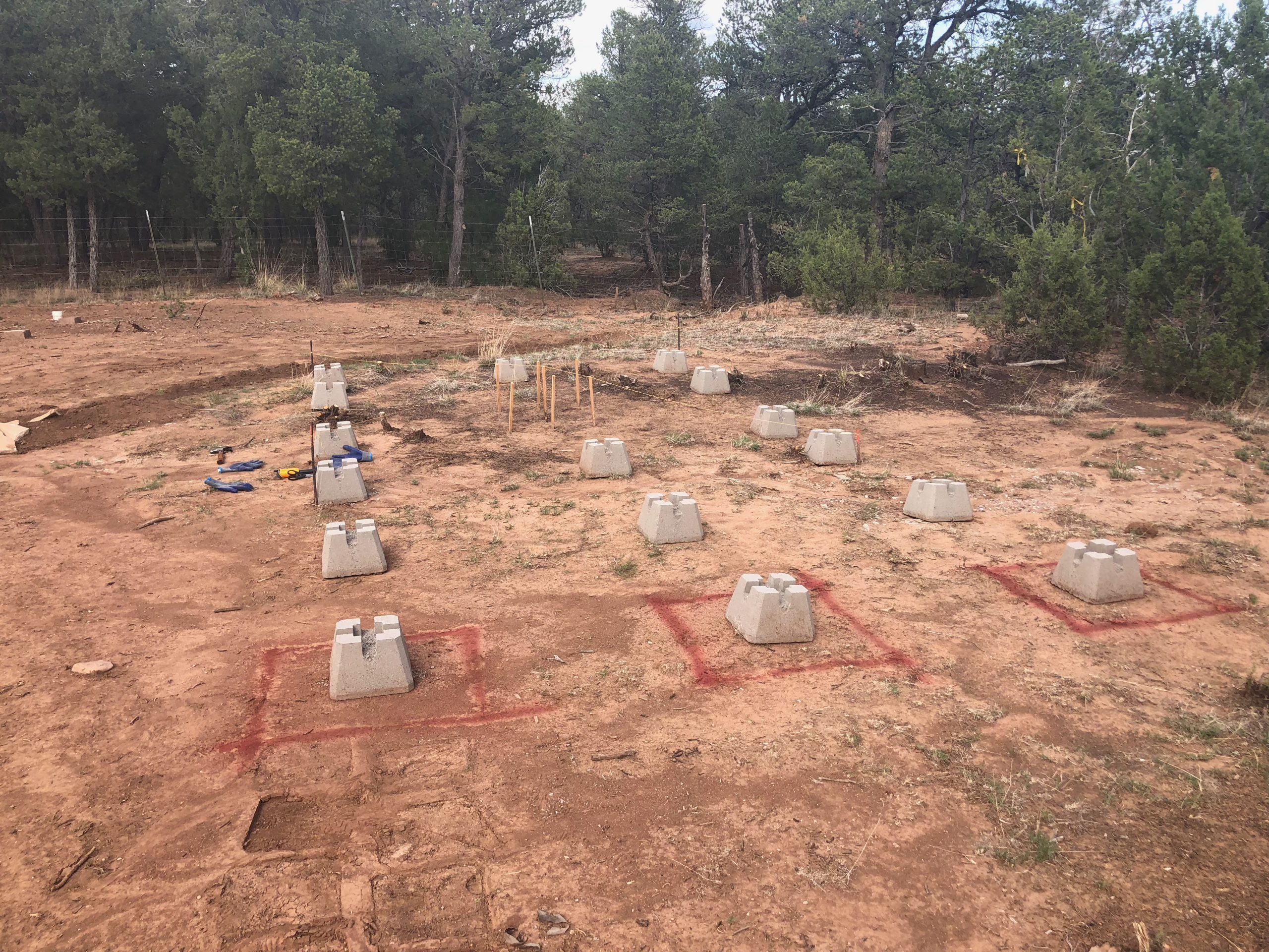
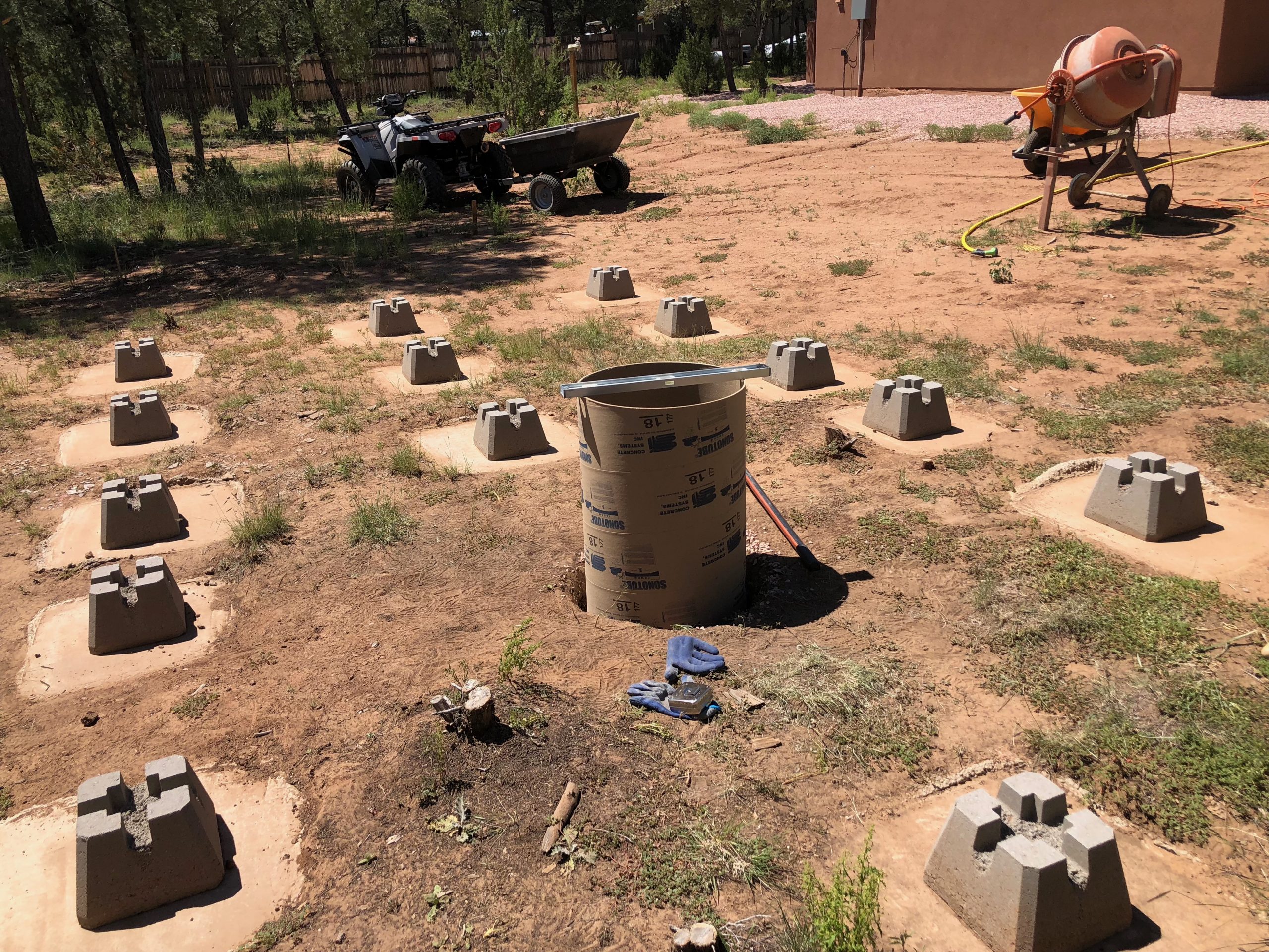
The first stage of construction began with laying out the positions of the precast deck blocks and marking the pier locations. Using red construction paint, I carefully measured and spaced the layout to match the observatory floor plan. Because the new structure was larger—10×18 feet compared to the 10×10 layout of my earlier Blue Ridge Observatory—I added support blocks down the center in addition to the perimeter, providing extra stability for the longer spans. These deck blocks would later support the beams for the floor joists and form the foundation of the roll-off structure.
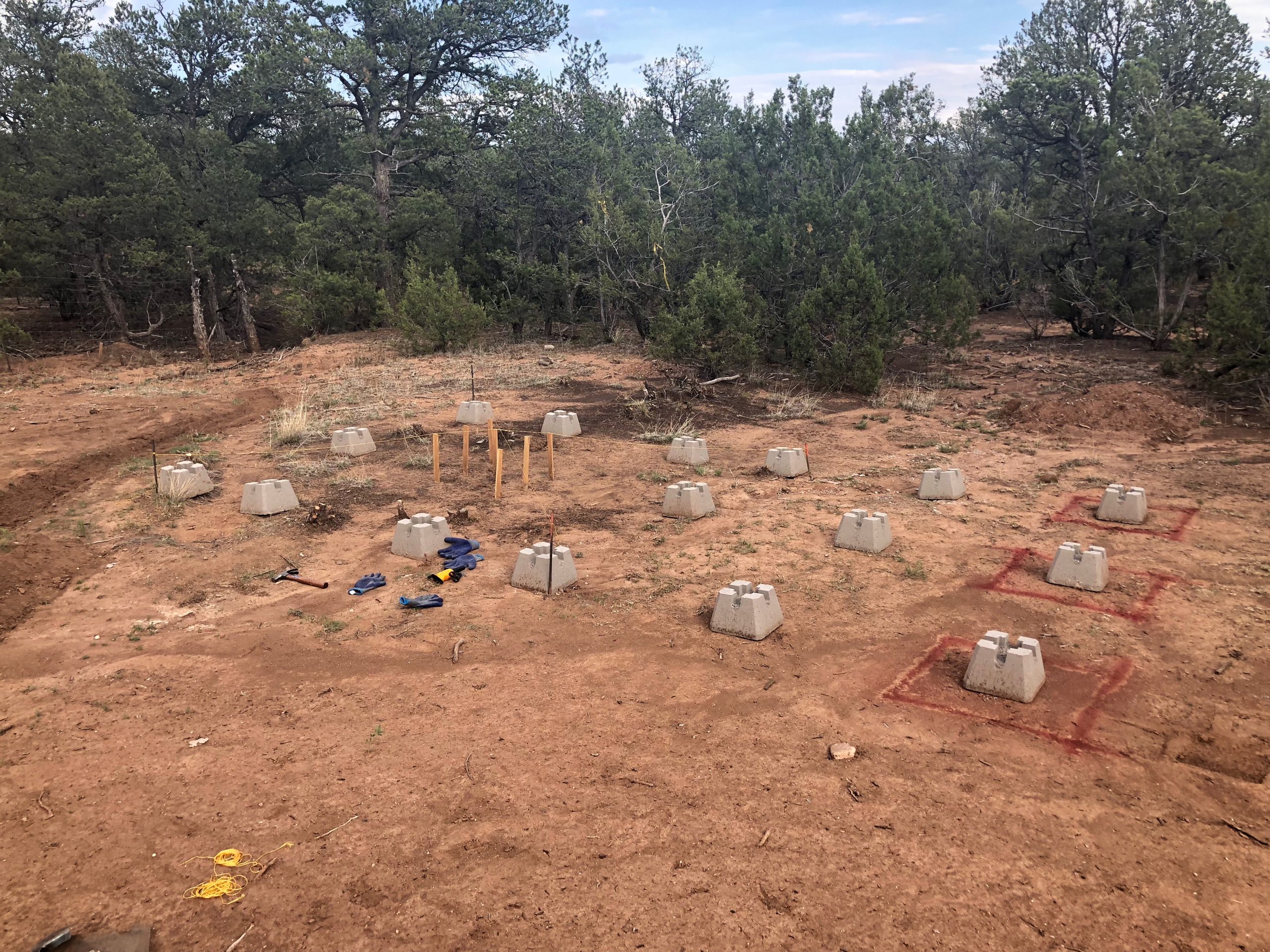
Once the layout was marked, I placed the deck blocks roughly in position along with a placeholder for the telescope pier. This dry run helped visualize the final footprint of the observatory and confirm spacing before committing to excavation and leveling.
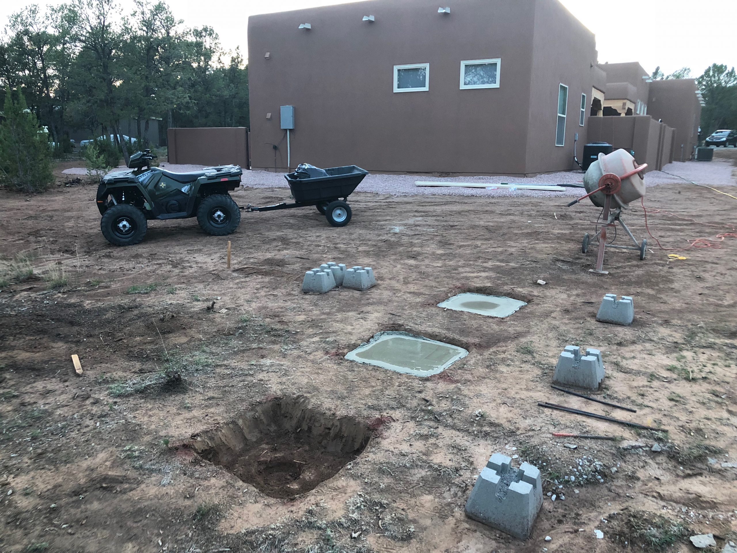
I began by digging the first three footer holes, each about two feet deep to help guard against frost heave and ground movement. The concrete pads I poured were intentionally oversized — giving them added strength, resistance to erosion, and allowing room to fine-tune the deck blocks for precise alignment.
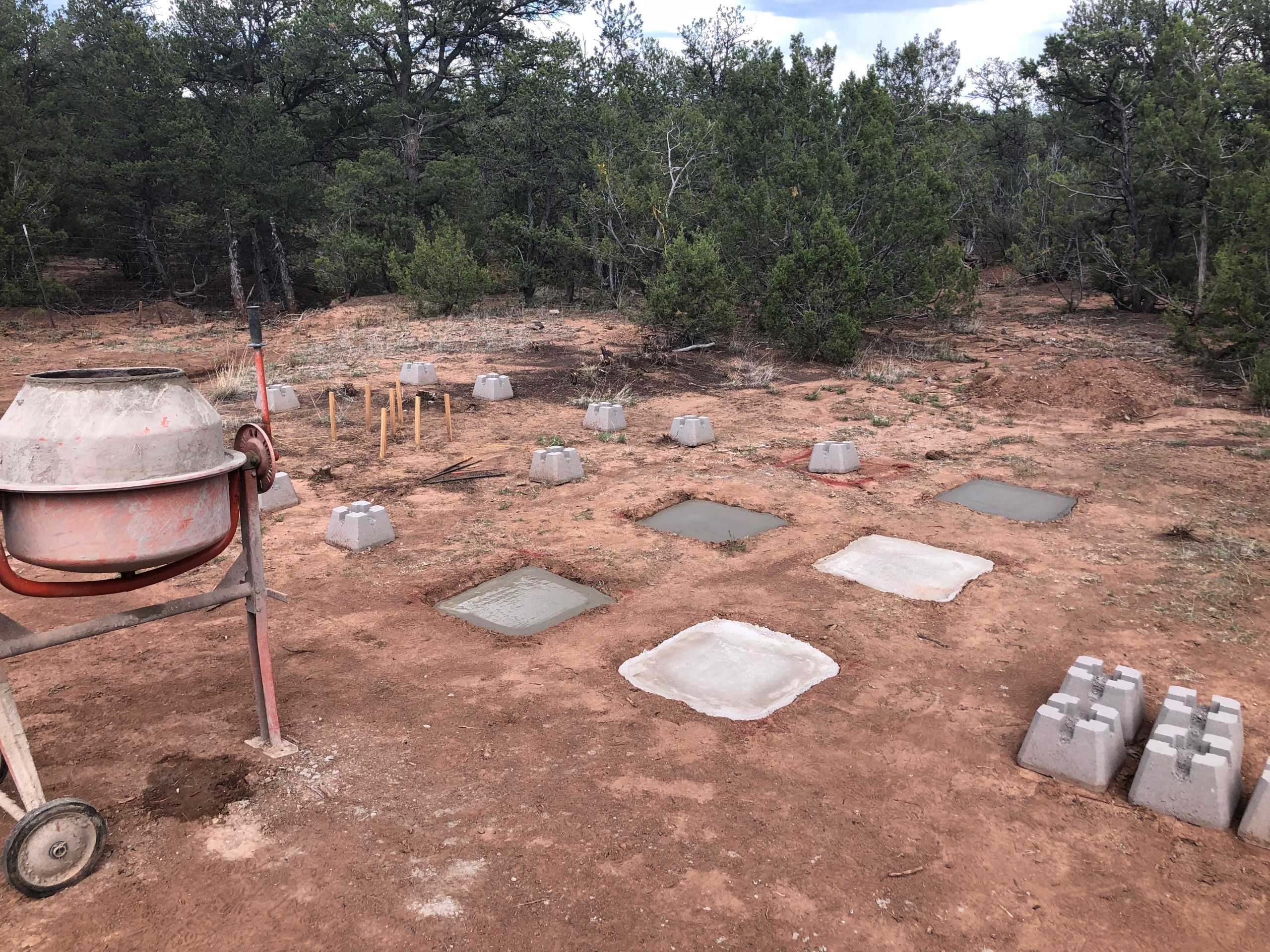
With the process underway, I continued digging and pouring the next set of oversized footers. Each hole was dug roughly two feet deep, then filled with concrete to create a broad, stable base. Each pad was carefully leveled as it was poured to ensure a flat and even surface. The added surface area helped distribute weight, resist erosion, and provided the flexibility to position the deck blocks with precision.
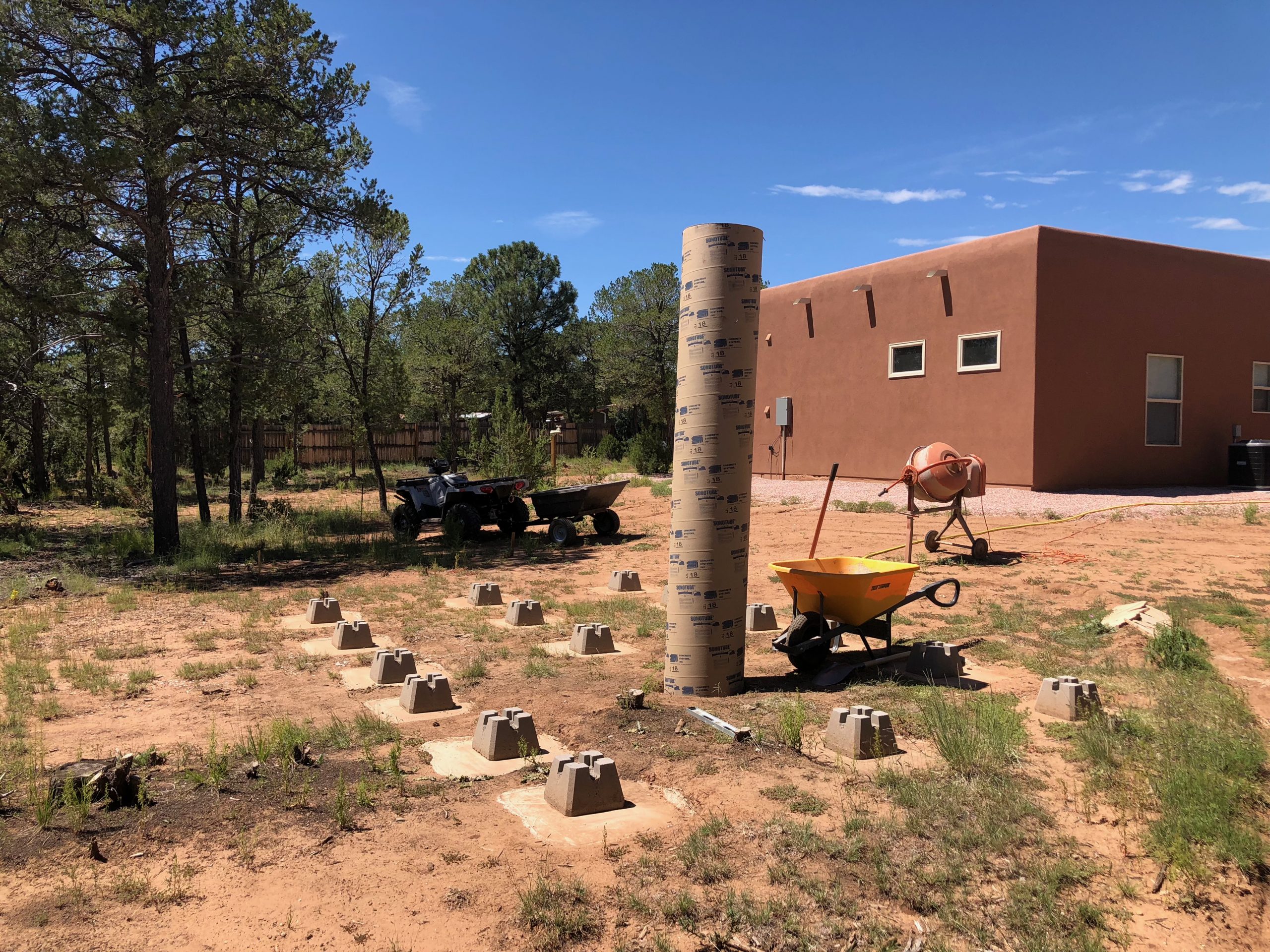
With most of the concrete pads now poured and cured, I placed and adjusted the deck blocks across the site. By this point, the layout was really coming into focus, revealing the full footprint of the observatory. Each block was leveled and aligned to ensure that the joists would sit securely and evenly. The surrounding tools and equipment give a good sense of the work still in progress, as the foundation neared completion.
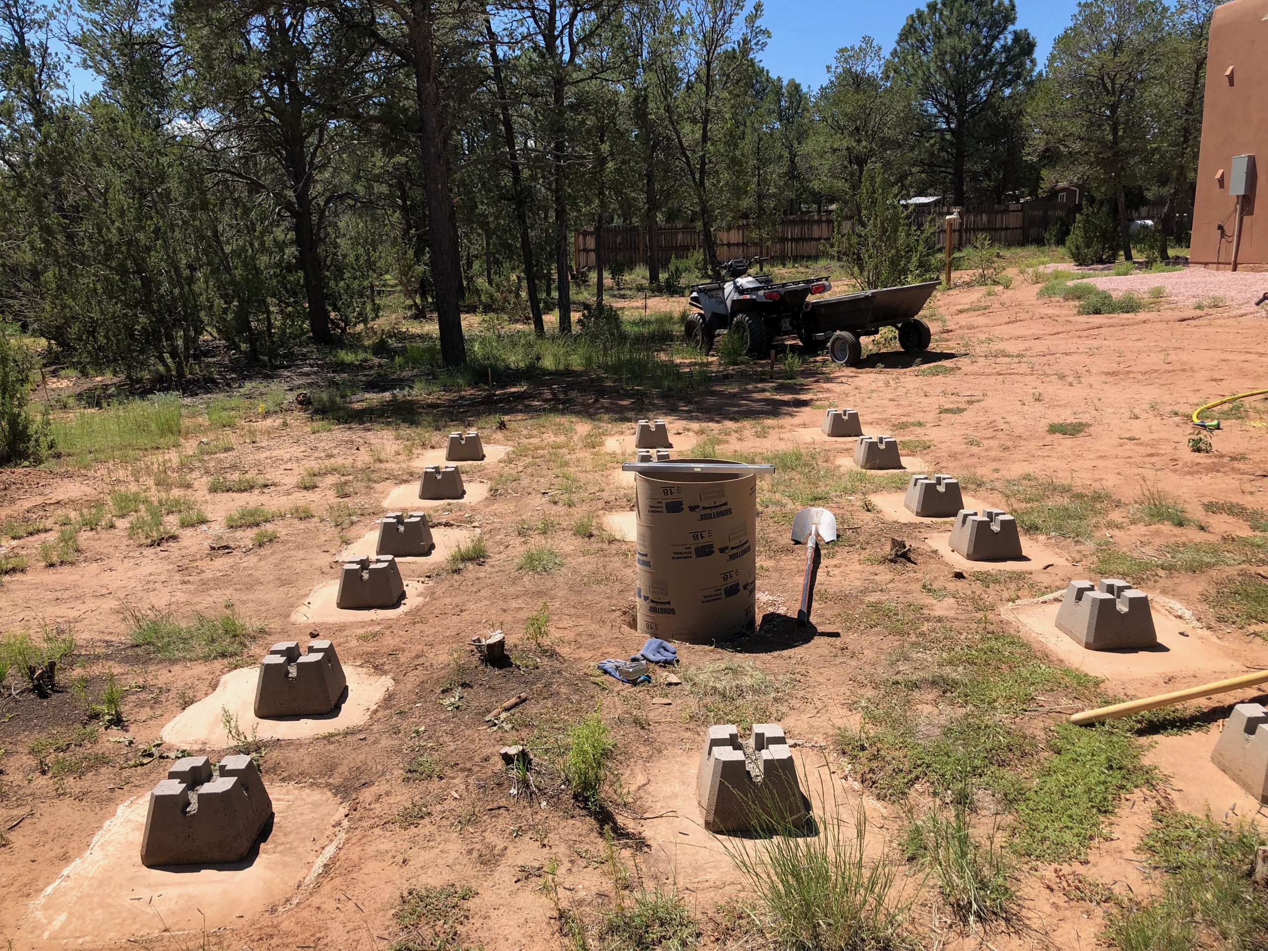
With all of the concrete pads poured and leveled, I placed the remaining precast deck blocks into their final positions. This stage marked the completion of the observatory’s foundational layout. The site was now ready for the next phase: framing and securing the floor structure on top of the stabilized, frost-resistant footings.
With the foundation complete, the next step was pouring the foundation for the telescope pier. I reused the same steel pier from Blue Ridge Observatory—an 8 5/8” diameter model originally purchased from SkyShed—designed to handle the combined weight of my 14” Schmidt-Cassegrain and mount, which totals over 200 pounds.
Since Mesa Vista uses a raised deck instead of a poured slab like Blue Ridge Observatory, I had to precisely calculate the pier’s height so the steel section would meet the bottom of the observatory floor. That meant cutting the Sonotube form to a custom length after factoring in the gravel base, concrete depth, and J-bolt assembly.
I dug the pier hole 48 inches deep to minimize frost heave and provide a stable footing. Although the ground here in Pecos is much softer than the rocky slate at Blue Ridge Observatory, the main challenge this time was working around dense, persistent tree roots. I used a mix of post hole diggers, a shovel, and a gas-powered auger to get it done.
Once the hole was cleared, I added a layer of gravel to the bottom for drainage and stability, leveled it carefully, and poured the concrete. I reused the original J-bolt template I had built for Blue Ridge Observatory to ensure accurate placement of the mounting hardware for the pier itself.
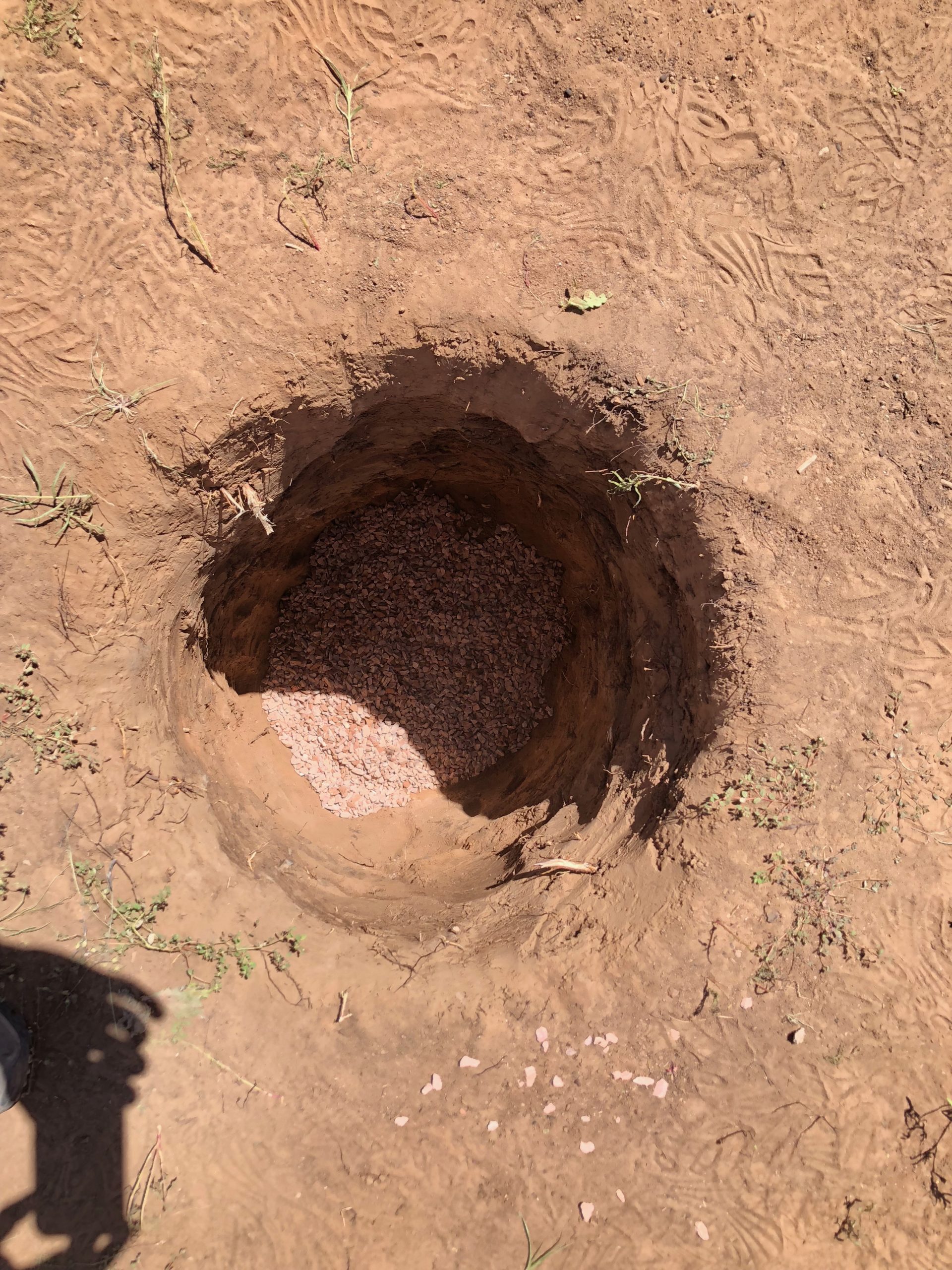
Digging the hole for the telescope pier was surprisingly easier than expected—thanks to the softer soil in Pecos—but I still had to contend with stubborn tree roots. I excavated to a depth of 48 inches to reduce the risk of frost heave and added a thick layer of gravel at the bottom to improve drainage and provide a stable base for the concrete pour.
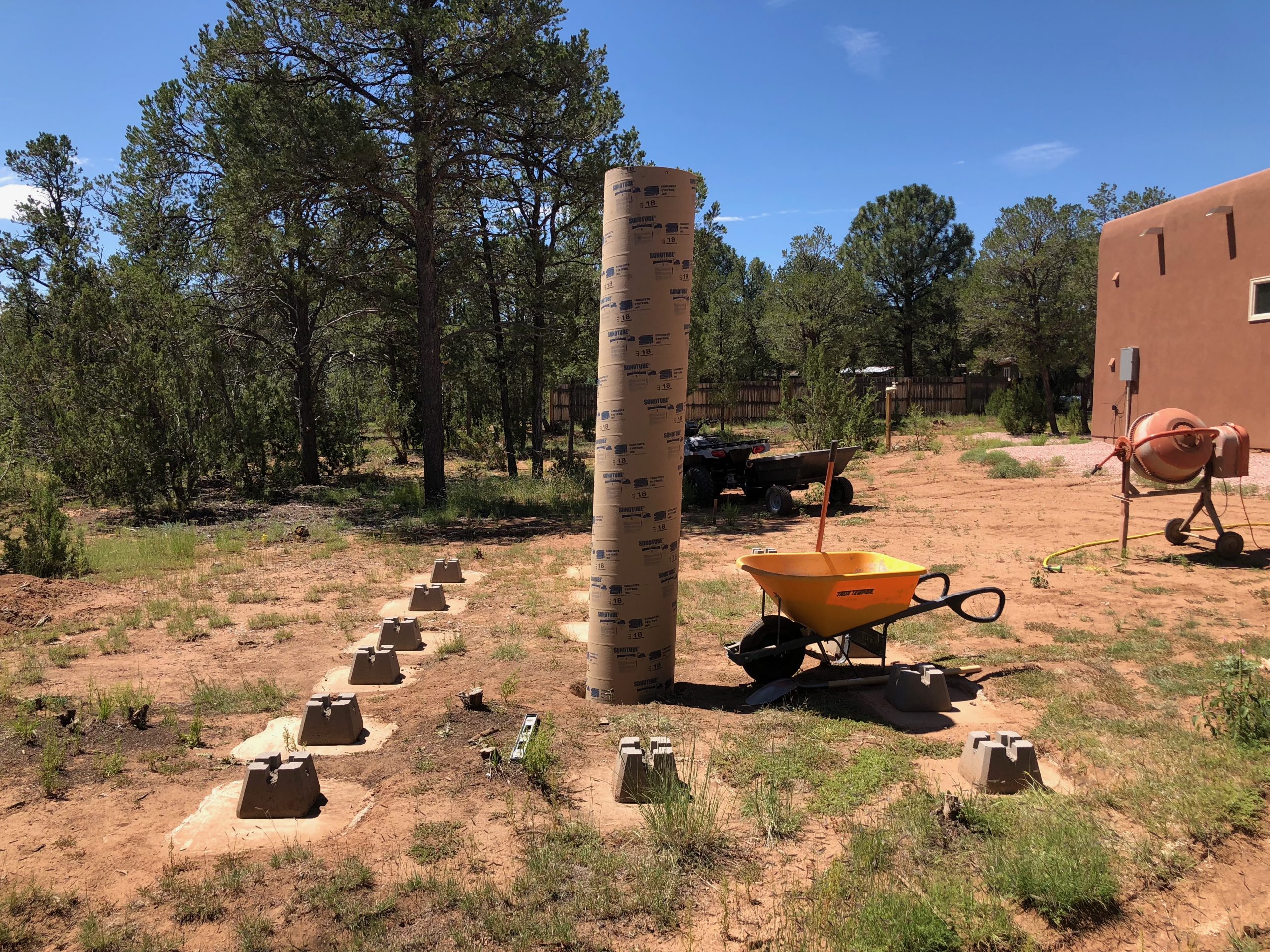
With the hole fully dug and a gravel base added for drainage and leveling, I positioned the 14” Sonotube and made sure it was vertically aligned. I cut the tube to a height that would bring the top of the concrete just under the future observatory floor. With tools and materials in place, I was ready to begin the pour.
Another view of the setup, showing the Sonotube in position with the work area prepped for pouring. The nearby mixer and wheelbarrow made it easy to batch and deliver the concrete directly to the form.
With the Sonotube trimmed to the correct height, the form was carefully leveled and stabilized. Getting this right was critical to ensure the steel pier would later align precisely with the floor level and telescope mount.
Another angle showing the trimmed and leveled Sonotube ready for the concrete pour. Final checks were made to ensure everything was plumb and aligned with the planned observatory floor height.
To ensure proper drainage and long-term ground stability, I began this stage by laying down a base of compacted gravel beneath the observatory’s footprint. The structure rests on pressure-treated 4×4 beams, each precisely cut and bolted to pier posts seated in stabilized deck blocks. Because the terrain has a noticeable slope, I spent a fair amount of time adjusting each pier height to maintain a level base. This part wasn’t as difficult as I expected—but it did require careful measuring and patience. A square and level floor is essential, since any misalignment here would cause major problems with the walls and the roll-off roof later on.
Once the 4×4 beams were leveled and locked in, I attached 2x6s around the perimeter to form a rigid box structure. I then ran additional 2×6 boards perpendicular to the beams to reinforce the frame and provide lateral stability. The interior joists were spaced evenly to create a grid—probably more supports than strictly necessary, but I had extra lumber and decided to make the floor exceptionally sturdy.
Special care was taken around the central telescope pier. I had to get creative with the framing to completely isolate the pier from the rest of the floor. The concrete pier doesn’t touch the floor structure at all, preventing vibrations from being transferred to the telescope.
Once the framing was complete, I installed OSB panels to form the subfloor. This gave me a strong, level, walkable platform—ready for the next phase: building the walls.
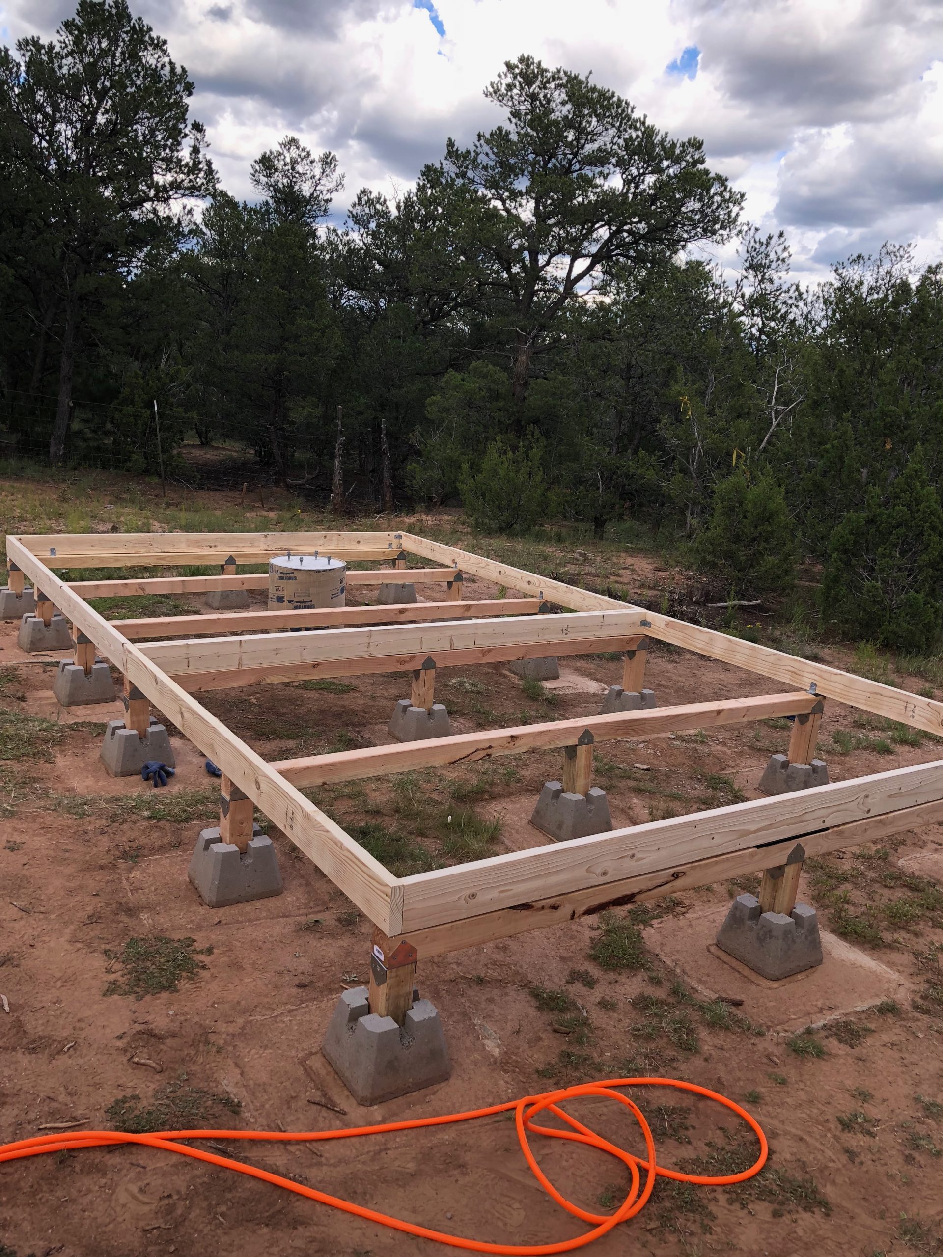
The floor framing is set on a grid of heavy-duty concrete deck blocks and pressure-treated 4×4 piers, carefully leveled to provide a stable base for the observatory structure. Joists are secured with metal brackets and oriented to maintain clearance around the pre-installed telescope pier, ensuring vibration isolation and load separation between the building and the instrument mount.
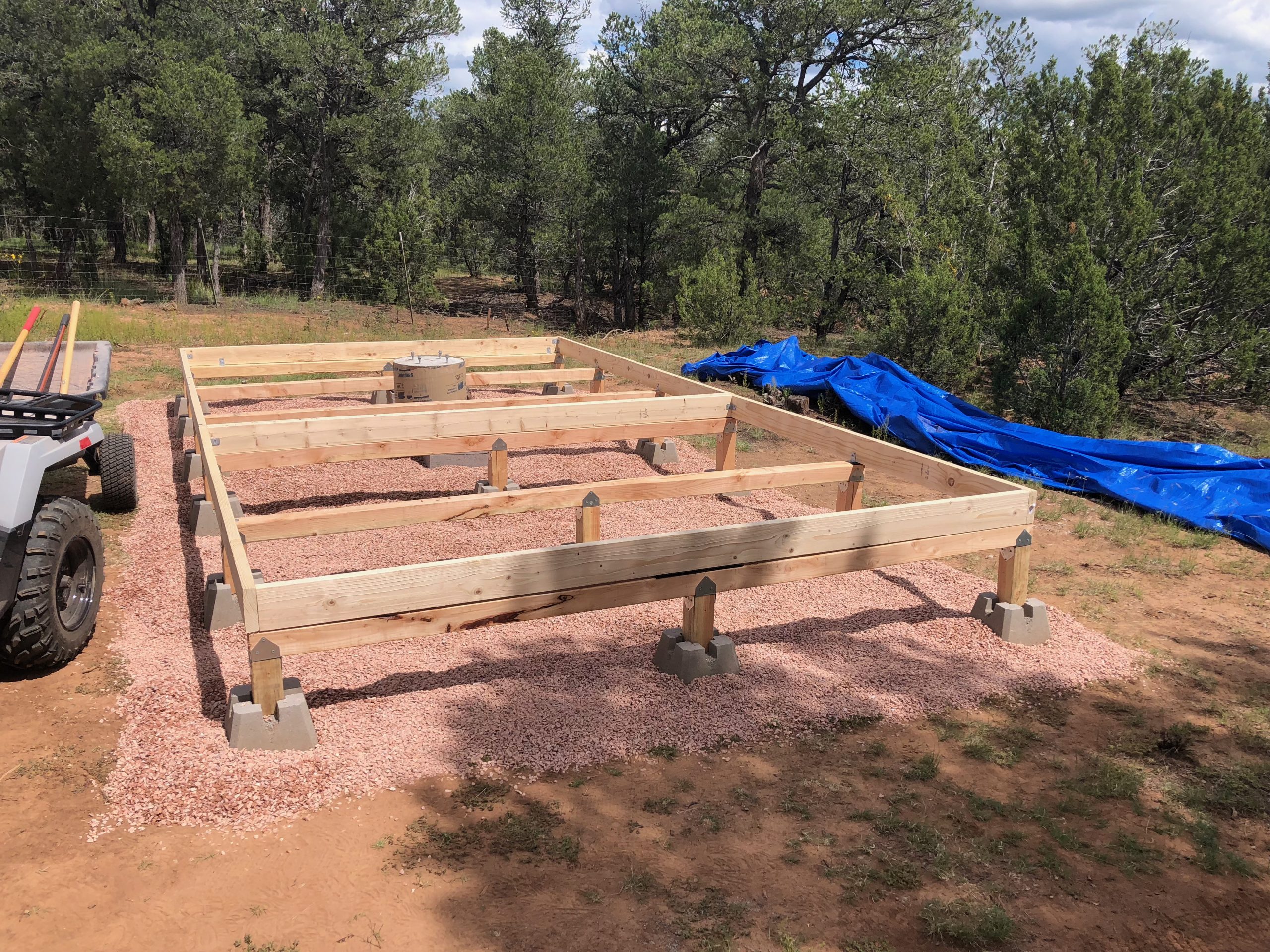
With framing in place, a thick layer of compacted gravel is added beneath the structure to improve drainage and minimize ground moisture intrusion. This helps preserve the pressure-treated floor framing over time while also reducing thermal updrafts and dust accumulation inside the observatory. The gravel bed extends beyond the perimeter to maintain a clean, dry work area during future construction phases.
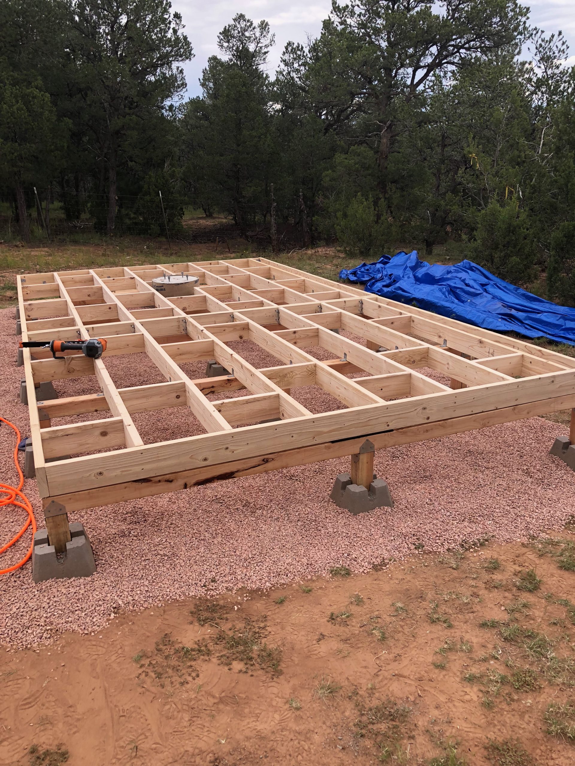
The full joist grid is now installed, with cross-bracing added for structural rigidity and even weight distribution across the floor system. Joists are fastened with metal hurricane ties for added wind resistance, and the design maintains a clear buffer around the central pier to ensure mechanical isolation for the telescope. The entire structure rests on the previously compacted gravel pad to mitigate moisture and maintain thermal equilibrium beneath the observatory.
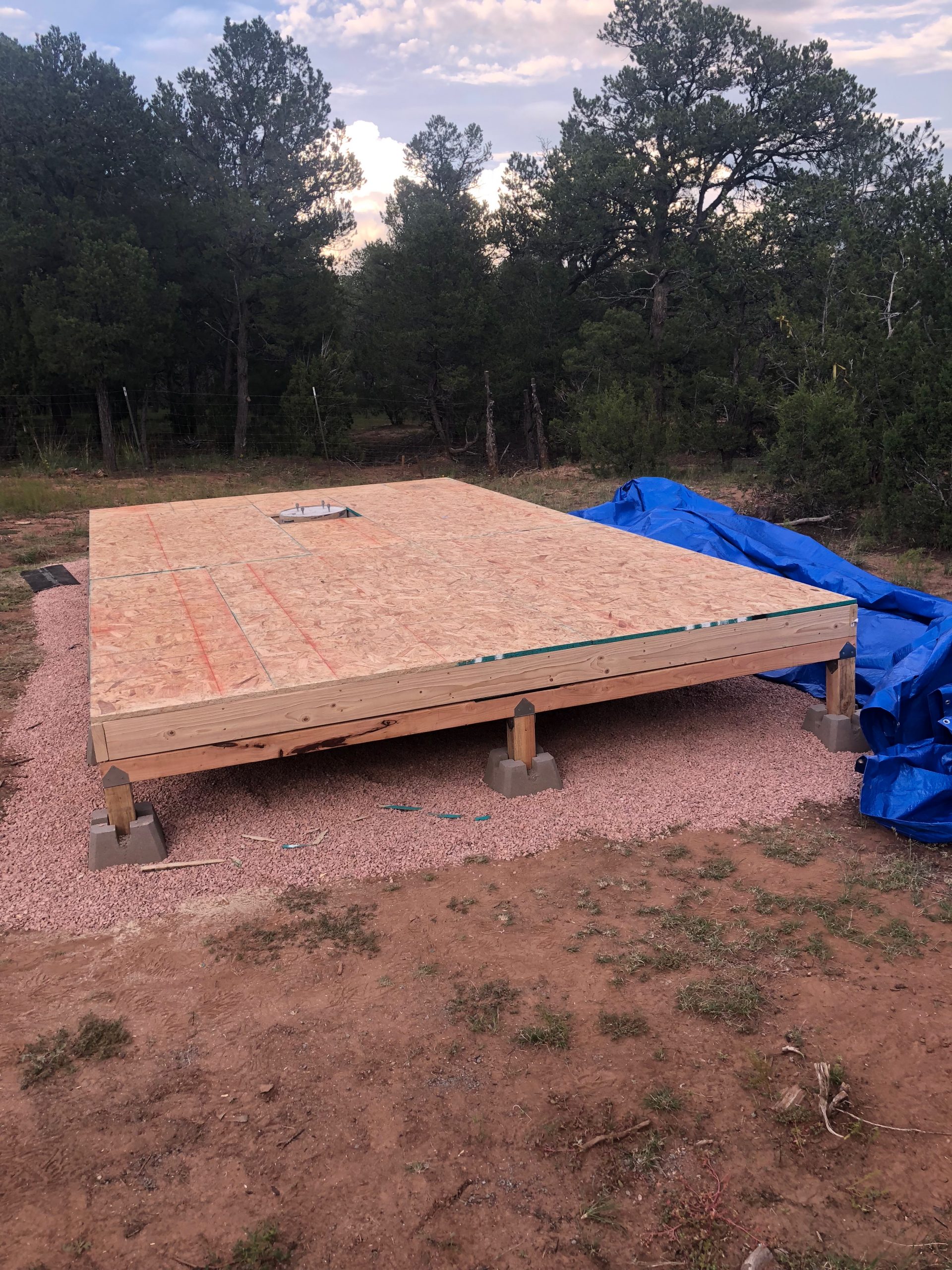
The subfloor is sheathed with standard OSB panels, carefully installed over the joist grid to create a strong and stable deck. Panels are laid with staggered seams for strength and fastened securely to minimize flexing. A cutout around the isolated concrete pier ensures the telescope mount remains mechanically decoupled from the structure, preserving image stability during long exposures.
The next phase was framing the walls. I started with the side and back walls, as they were the simplest to lay out. The back wall includes a single small window in the warm room, but the front wall required more planning since it incorporates a standard-sized entry door and two windows. Wall height in a roll-off roof observatory is always a balancing act—it’s influenced by the telescope pier height and how much of the sky you’re willing to obscure. My previous observatory, Blue Ridge, had 6-foot walls, but for Mesa Vista Observatory, I opted for 7-foot walls. The decision was easy: with surrounding trees already blocking the lower sky, shorter walls wouldn’t have improved visibility and would have complicated construction. The taller walls also allowed me to use off-the-shelf windows and doors from Home Depot, avoiding the need for custom builds.
Once the exterior walls were framed and the openings cut for the doors and windows, I moved on to the interior. I framed a divider wall between the 10×10 telescope room and the 8×10 warm room, including an interior window between the two so I could visually monitor the telescope while operating it remotely. With all framing complete, I sheathed the exterior walls in OSB and made precision cutouts for the door and windows. Finally, I wrapped the entire structure in a titanium weather barrier to provide long-term protection from wind and moisture.
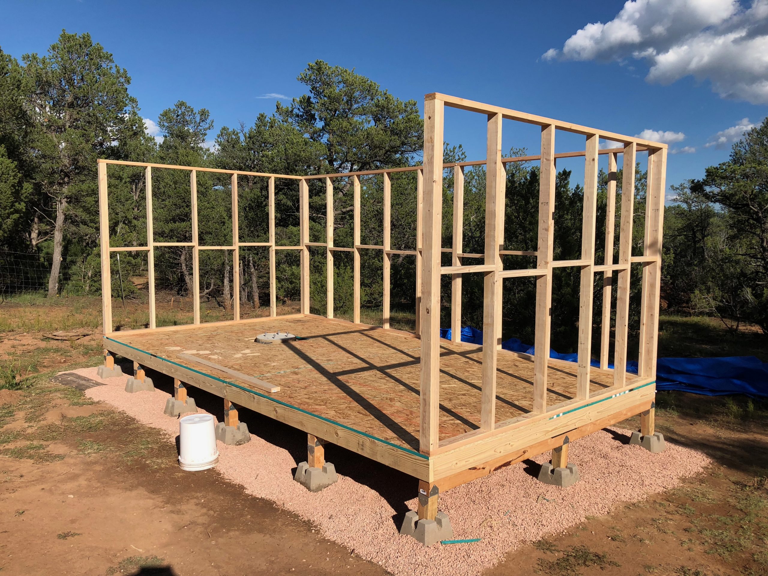
Framing begins with the back and side walls, which are the simplest sections to lay out. The 2×4 studs are spaced at standard 16-inch intervals, with rough openings framed for a small rear window and one side window in the warm room. The 7-foot wall height was chosen to simplify construction, allow for standard door and window sizes, and match the tree line—ensuring no additional sky would be gained by going shorter.
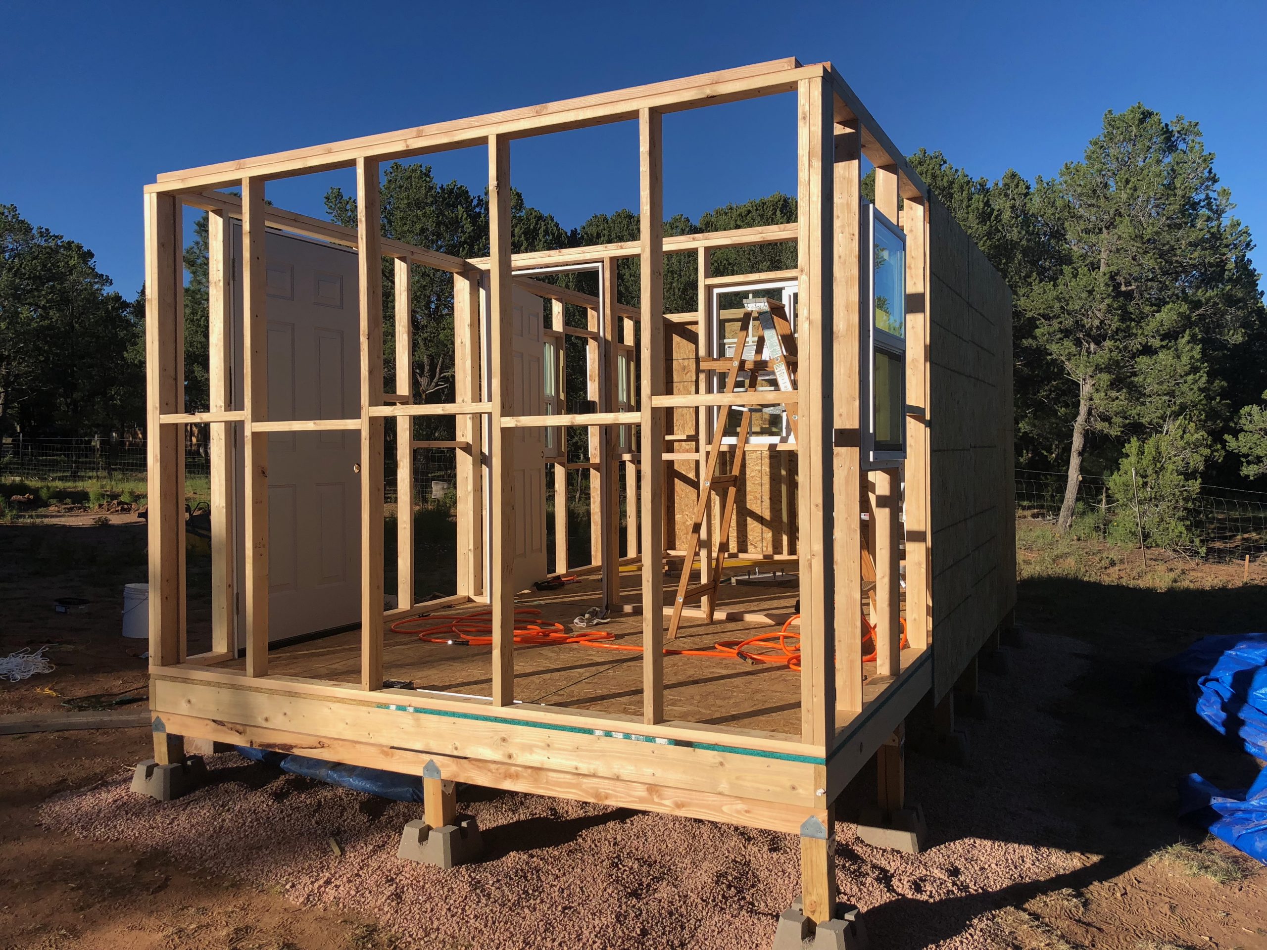
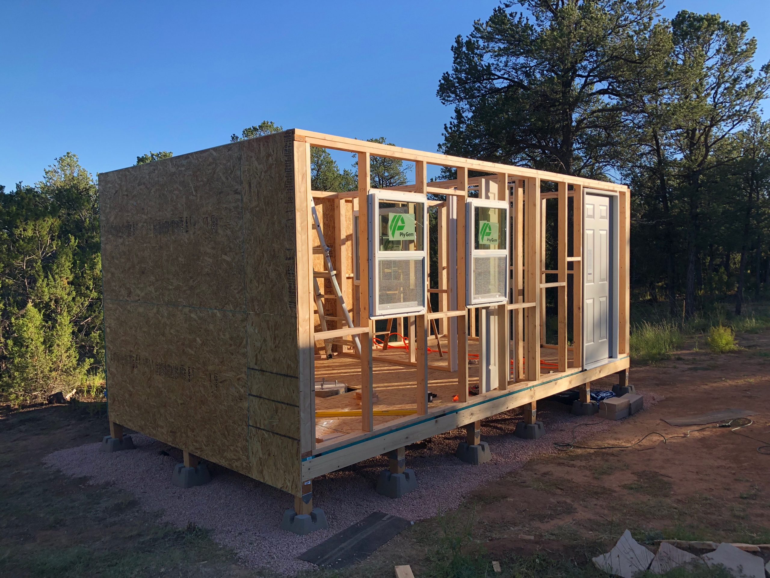
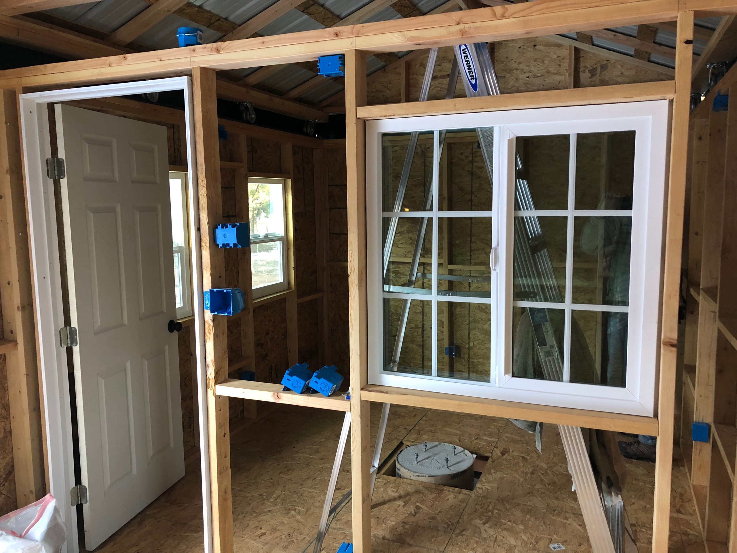
The front wall is now framed with rough openings for the main entry door and dual front-facing windows. The rear wall has been fully sheathed, and the warm room’s side window is in place. Inside, the partition wall between the 10×10 telescope room and the 8×10 warm room is framed and now features both the interior window and a standard interior door, allowing clear visibility and easy access between the two spaces.
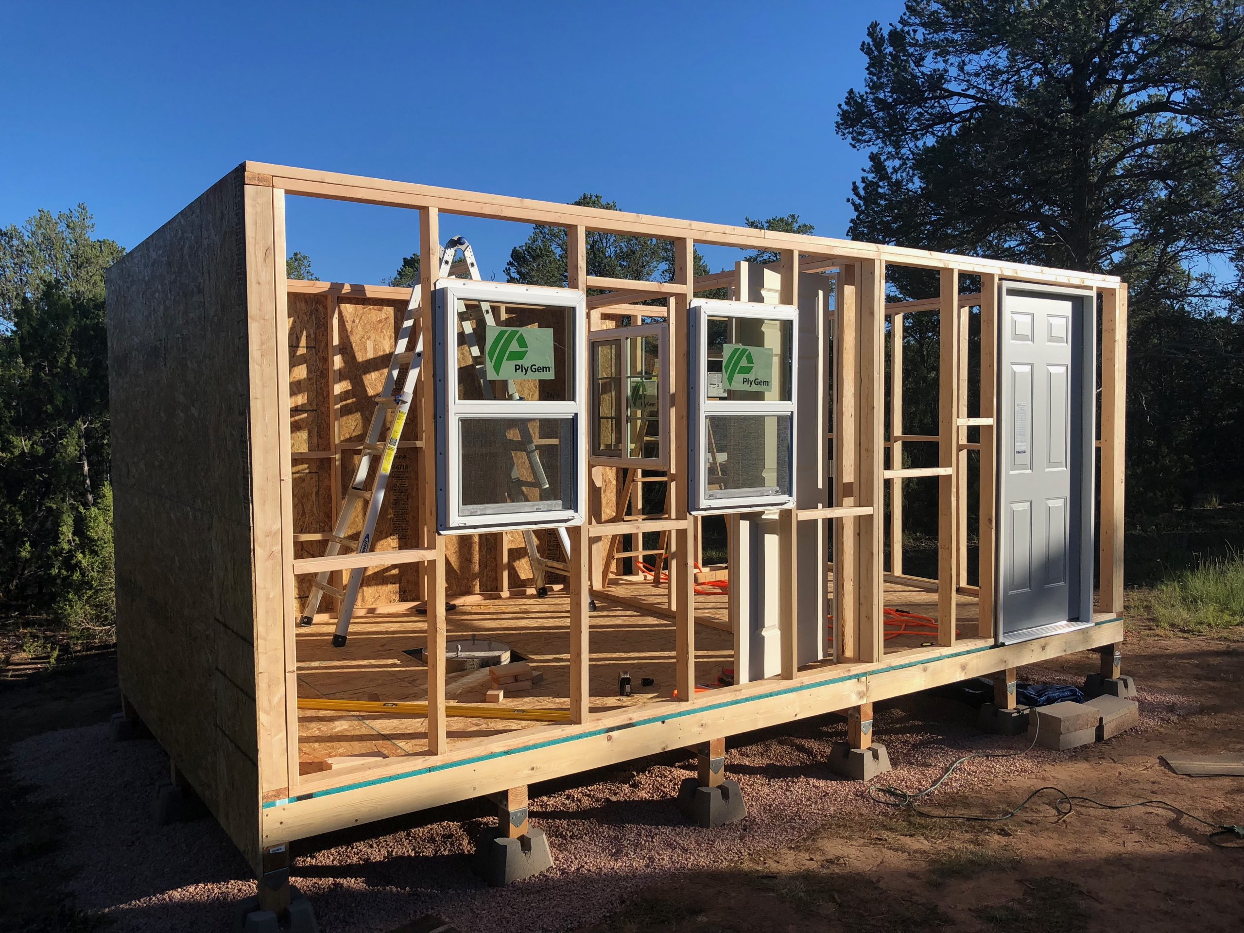
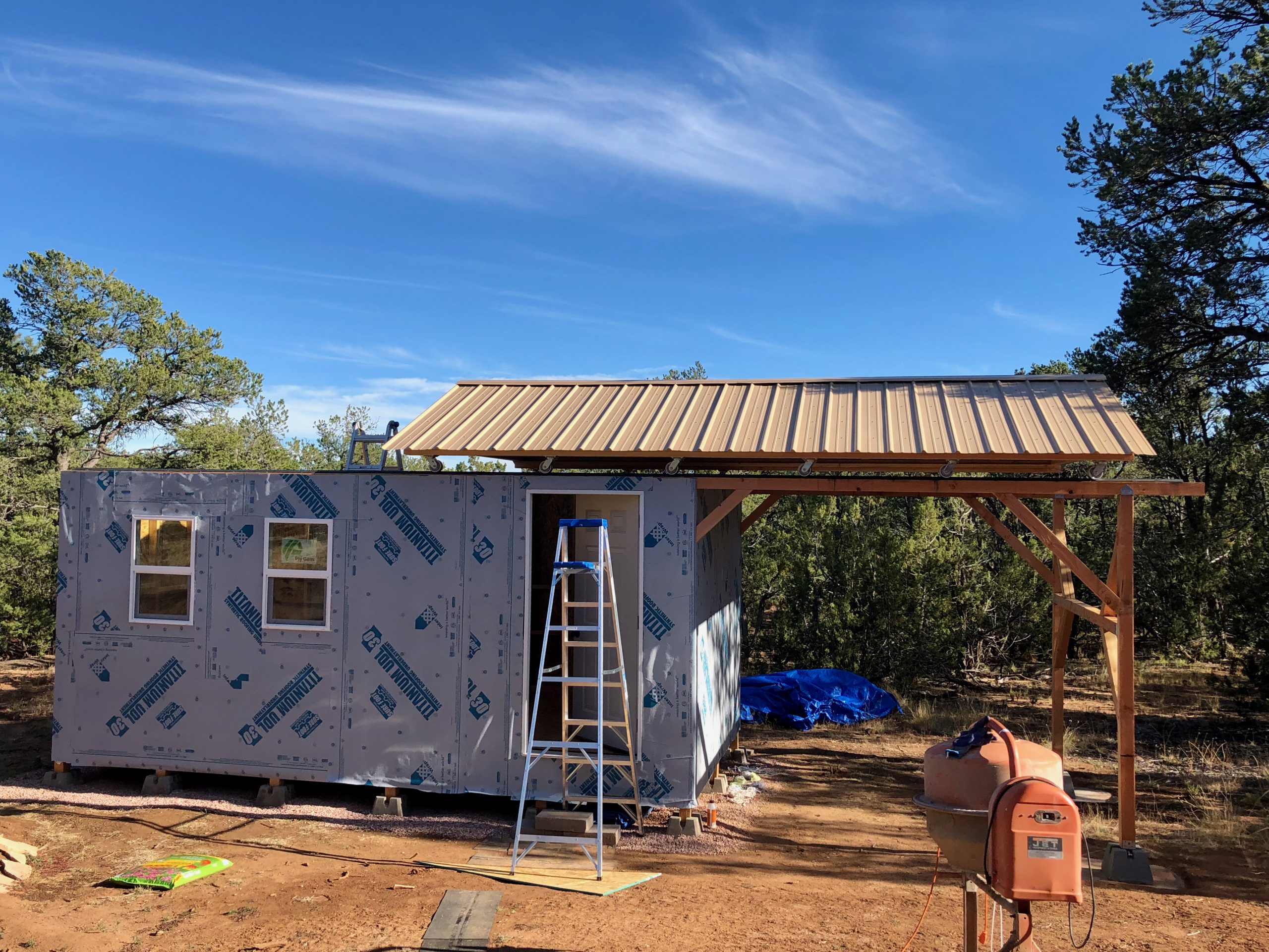
With exterior elements taking shape, both front-facing windows and the main entry door are now installed. The windows are standard Ply Gem units, and the entry door is a pre-hung model—eliminating the need for custom sizing. OSB sheathing has been completed on the rear and side walls, and interior framing continues to define the layout of the telescope and warm rooms. The structure is rapidly approaching the point where exterior wrapping and roof framing can begin.
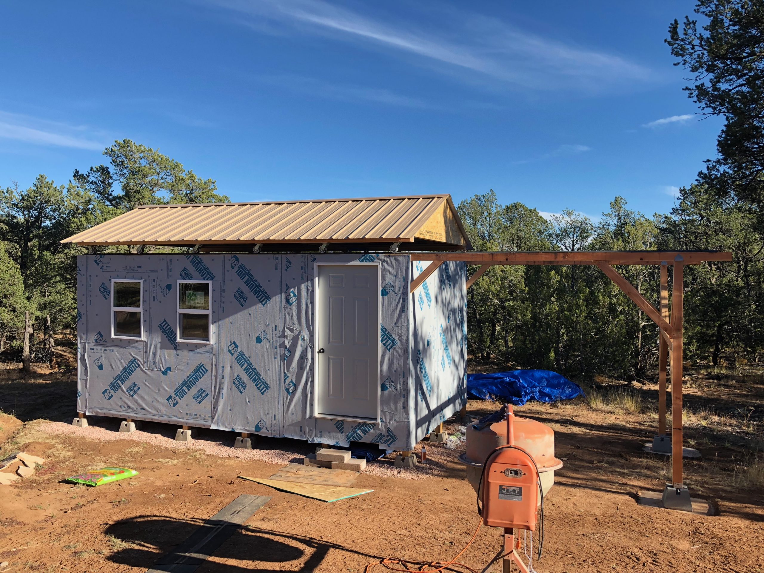
Sheathing progresses with full OSB coverage wrapping down over the floor framing and 4×4 rim joist, providing added structural rigidity and enhanced protection from wind and moisture. This approach encloses the framing cleanly, leaving only the vertical support piers exposed above the gravel base. With both front windows and the entry door now installed, the structure is fully defined and nearly ready for weather wrapping.
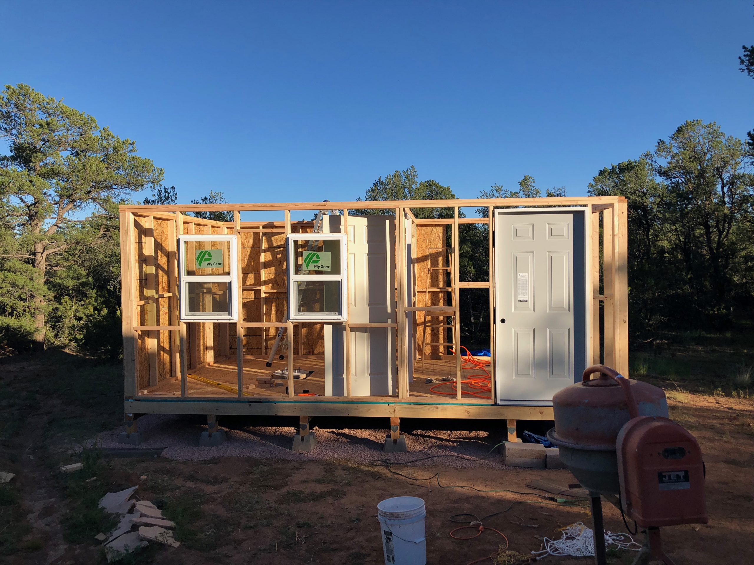
A head-on view of the front wall shows both Ply Gem windows and the pre-hung entry door fully installed, with portions of the interior and exterior sheathing complete. The interior partition wall, visible through the open framing, clearly separates the warm room on the left from the telescope room on the right. This layout ensures an efficient workflow between observing and control spaces while keeping the equipment environment thermally and physically isolated.
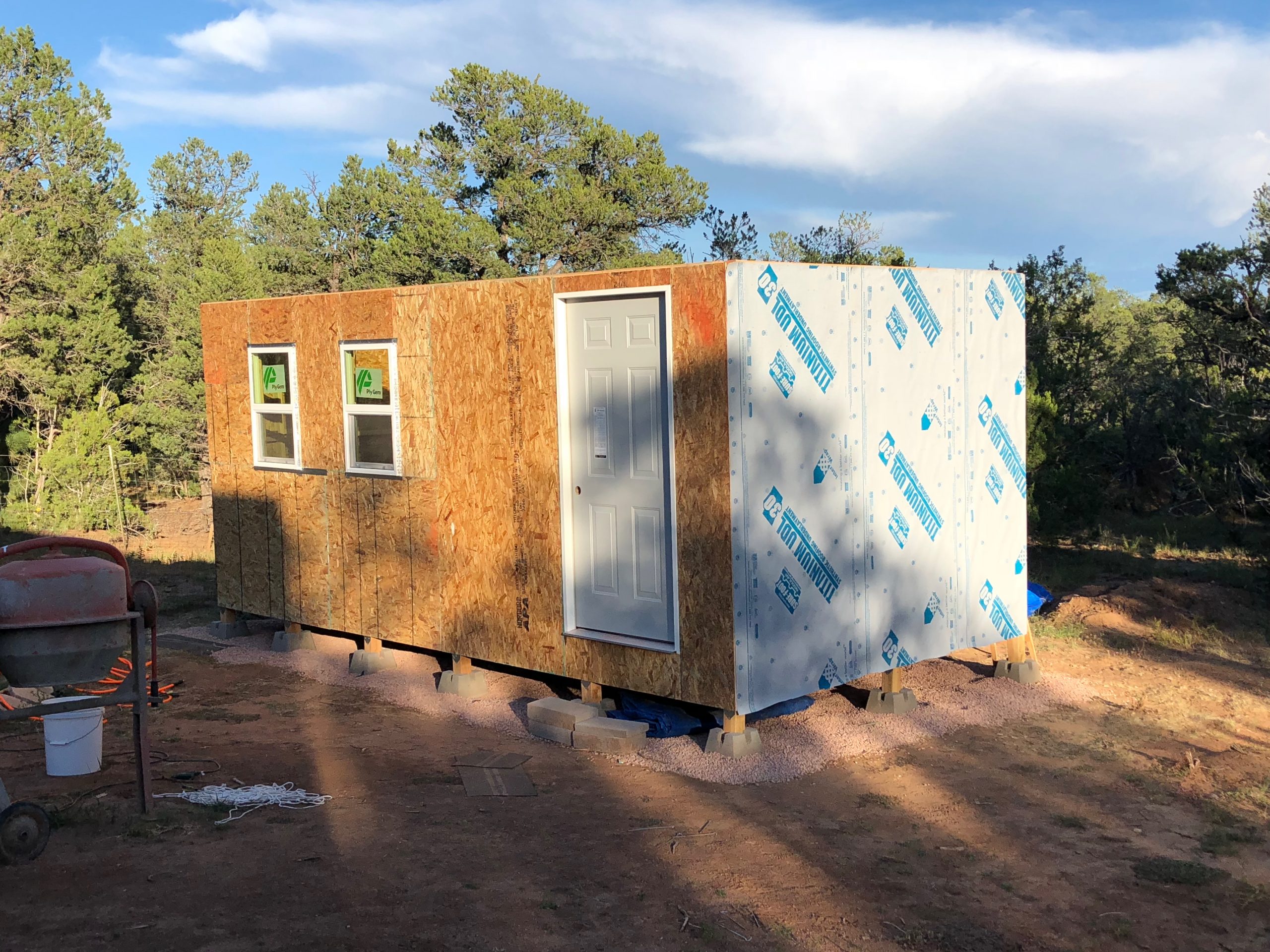
With all OSB sheathing now installed, the observatory structure is fully enclosed and ready for weatherproofing. The titanium building wrap, visible on the right side, has been partially applied to create a durable moisture and wind barrier beneath the final siding. This synthetic wrap adds an extra layer of protection for the structure’s framing, ensuring better performance in New Mexico’s variable mountain weather conditions.
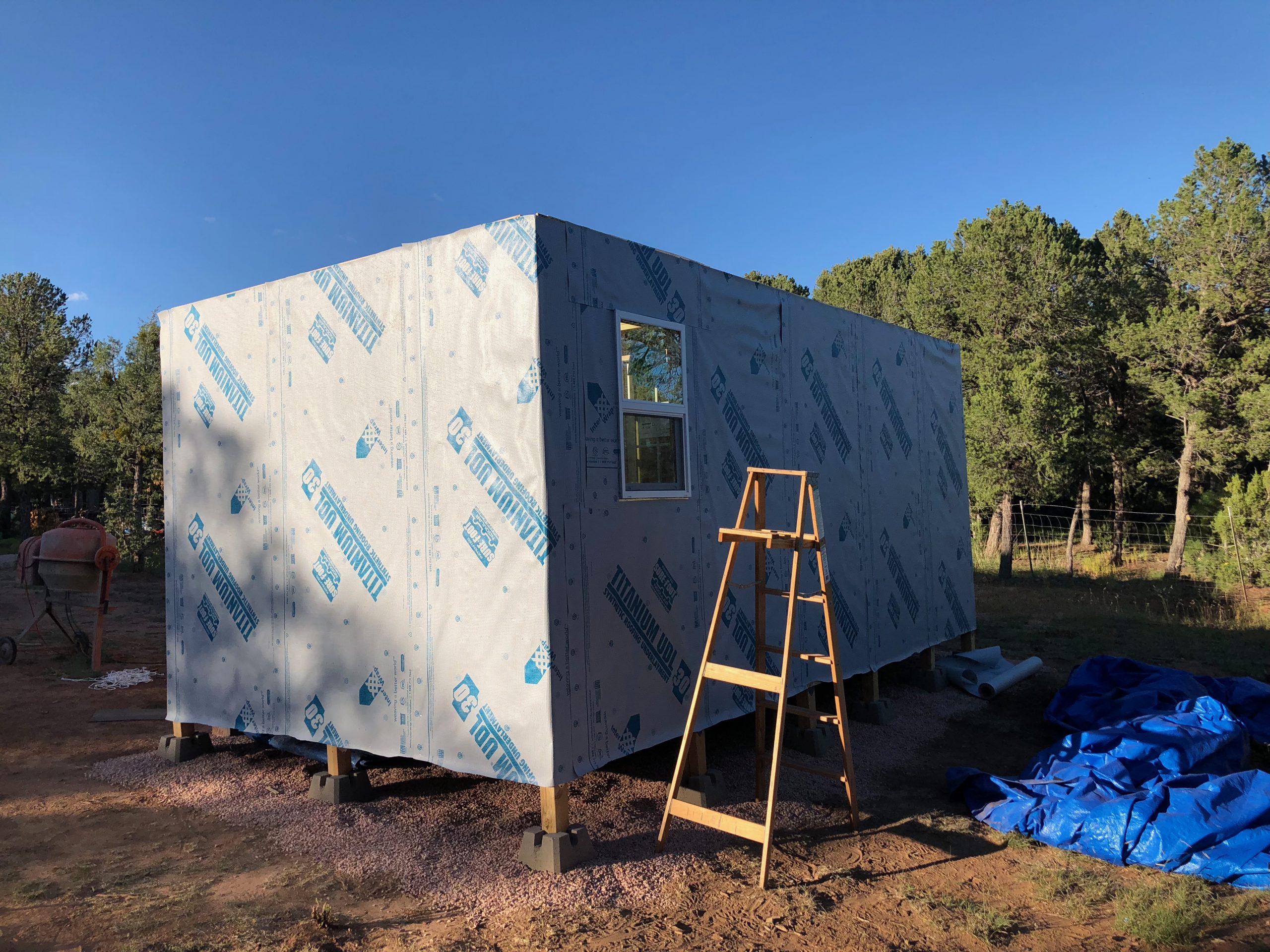
From the rear, the structure is now fully wrapped in titanium weather barrier, sealing the entire observatory shell against the elements. The small window in the warm room is now installed, completing all door and window placements. With the sheathing and wrap finished, the observatory is well-protected and ready for the next phase: framing the roll-off roof.
The roll-off roof was the most complex phase of the build, requiring careful alignment, structural support, and smooth mechanical movement. The first step involved constructing the extended support rails that the roof rolls onto when fully open. Pressure-treated 4×4 beams were securely fastened to the front and rear wall headers, with careful attention paid to keeping them perfectly level and aligned. Support braces and cross beams were added for reinforcement, and the outer vertical posts were anchored to concrete pads using adjustable deck blocks, allowing future height adjustments to compensate for settling.
Once the support system was complete, I built the main roof box frame and installed steel caster wheels along each side. These casters roll in grooved angle iron tracks, custom-fabricated locally to precise dimensions. With six casters per side, the system evenly distributes the roof’s weight. After lifting the assembled roof box onto the rails and confirming smooth travel, I framed and installed three roof trusses—two at each end and a third offset to avoid obstructing vertical telescope positions when the roof is closed. Horizontal cross braces were added both for rigidity and to simplify attachment of the roofing panels.
I chose a light-colored metal roof for its durability and low thermal gain, cutting panels as needed with an air-powered sheet metal cutter. With the roofing and ridge cap installed, the structure rolled cleanly on and off the rails. Unlike my previous design at Blue Ridge Observatory, where the rollers sat within the side walls, Mesa Vista uses a top-mounted roller design to reduce lateral stress and avoid long-term wall warping. To close the resulting side gap between the observatory and the moving roof, I attached 1×12 boards to the outer edge of the roof box, which overhang just enough to bridge the gap while still clearing the rails during movement.
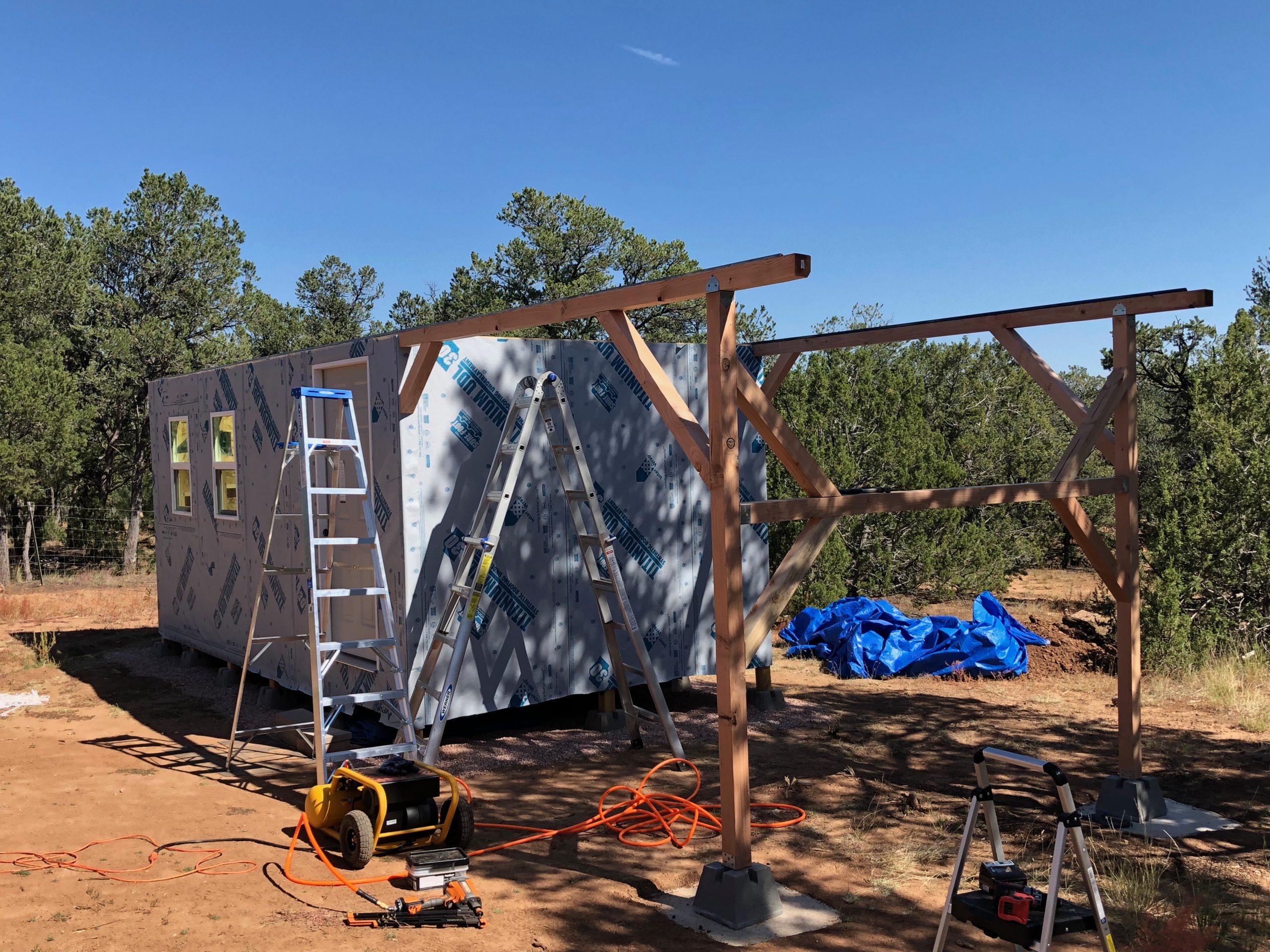
Construction of the roll-off support system begins with installation of the outer 4×4 beams and braces that will carry the roof when fully open. These pressure-treated beams are anchored to concrete pads using adjustable deck blocks to allow fine-tuning of the height if settling occurs over time. Each vertical post is reinforced with diagonal and horizontal cross-bracing to handle the full weight of the roof in its open position. Leveling and alignment at this stage were crucial to ensure the caster rails would operate smoothly later on.
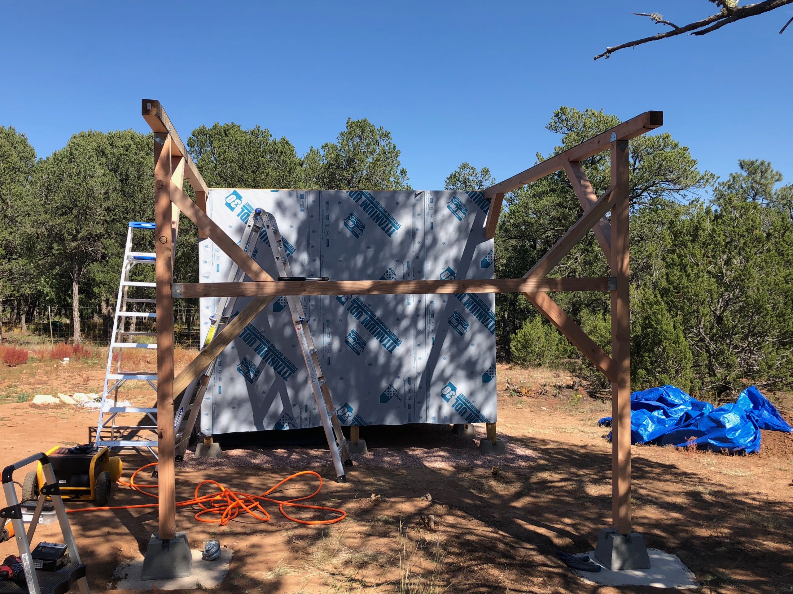
A front-facing view of the completed roll-off rail support system shows the full structure of the pressure-treated 4×4 beams and their reinforced bracing. The top beams are carefully aligned with the observatory’s wall headers to ensure smooth track installation later. Each vertical post rests on a concrete pad with an adjustable deck block riser, allowing future fine-tuning of roof alignment in case of ground settling or seasonal shift.
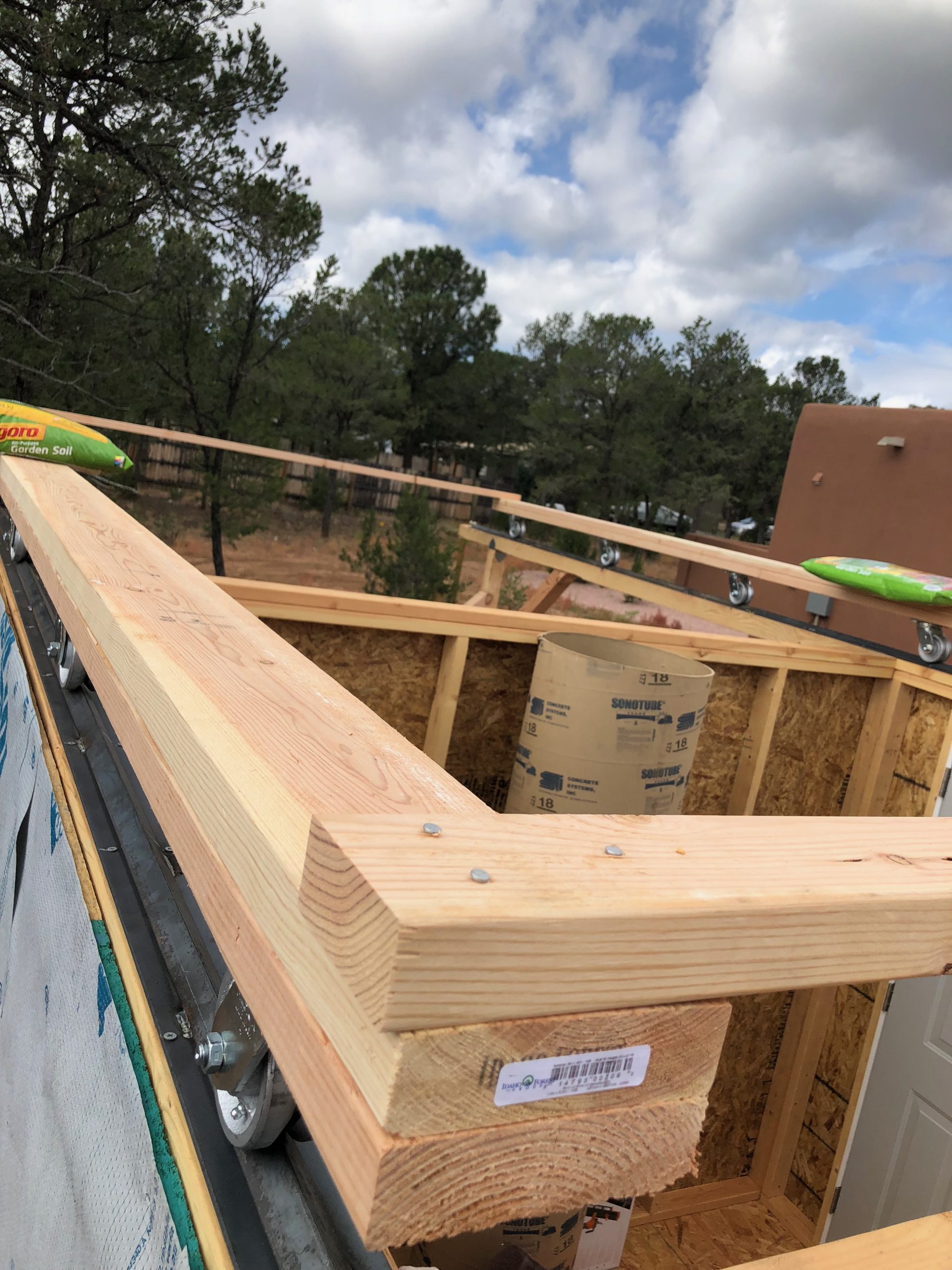
The roof box frame is now fully constructed and sitting on its caster system. Each side rides on six steel wheels seated within custom-fabricated grooved angle iron tracks for smooth and stable movement. The doubled-up 2x lumber and corner reinforcement provide rigidity to handle the weight of the roof panels and trusses. Temporary ballast (courtesy of some potting mix) helped keep the structure secure during windy conditions before the full roof was installed.
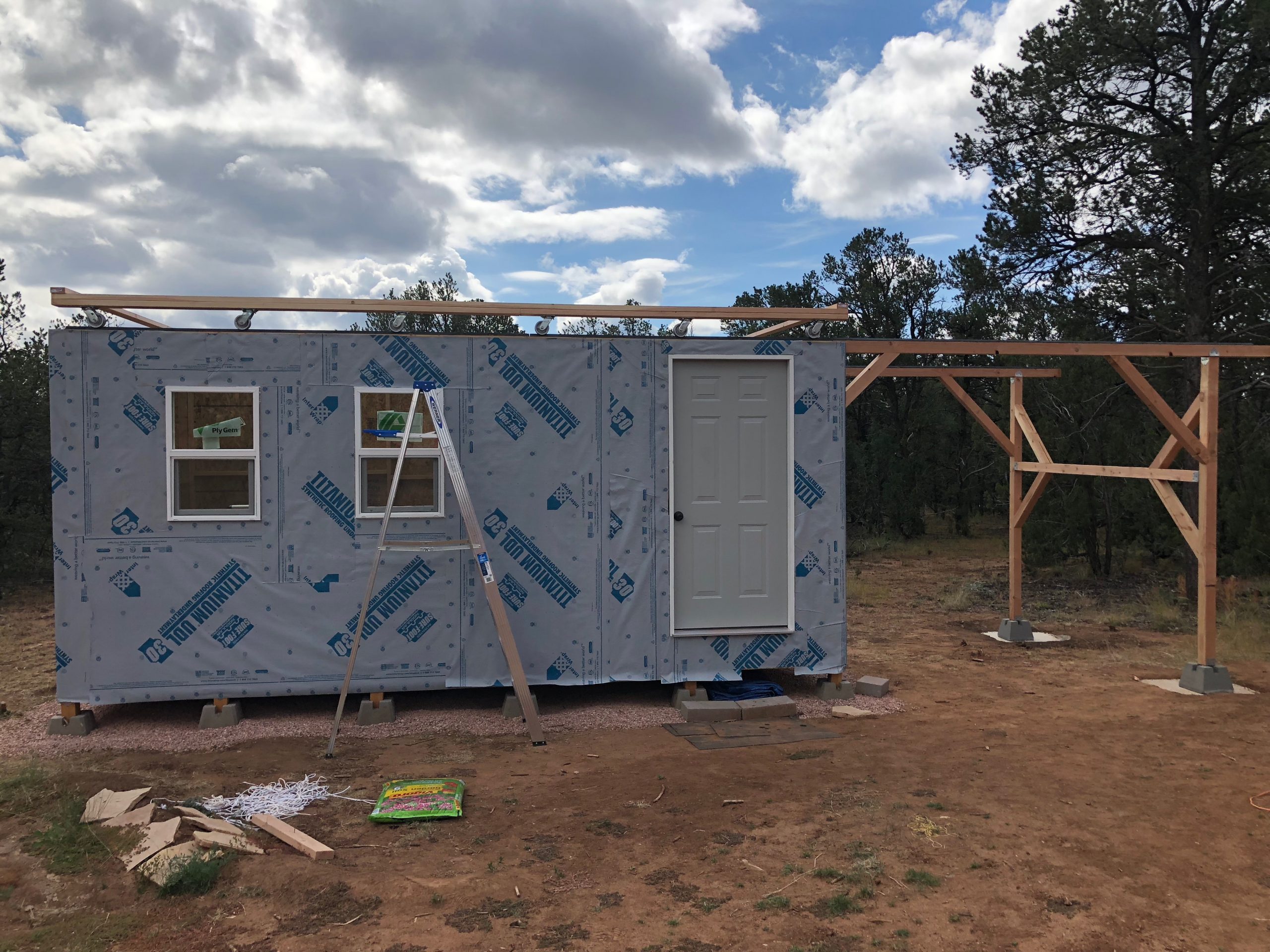
The roof box is now positioned in its fully closed state atop the observatory walls, demonstrating how the caster wheels ride smoothly along the grooved angle iron rails. This alignment confirms that the roof will be able to roll off cleanly onto the extended support structure when opened. The system is fully self-contained and decoupled from the observatory walls—minimizing stress on the structure and allowing for smooth, reliable operation over time.
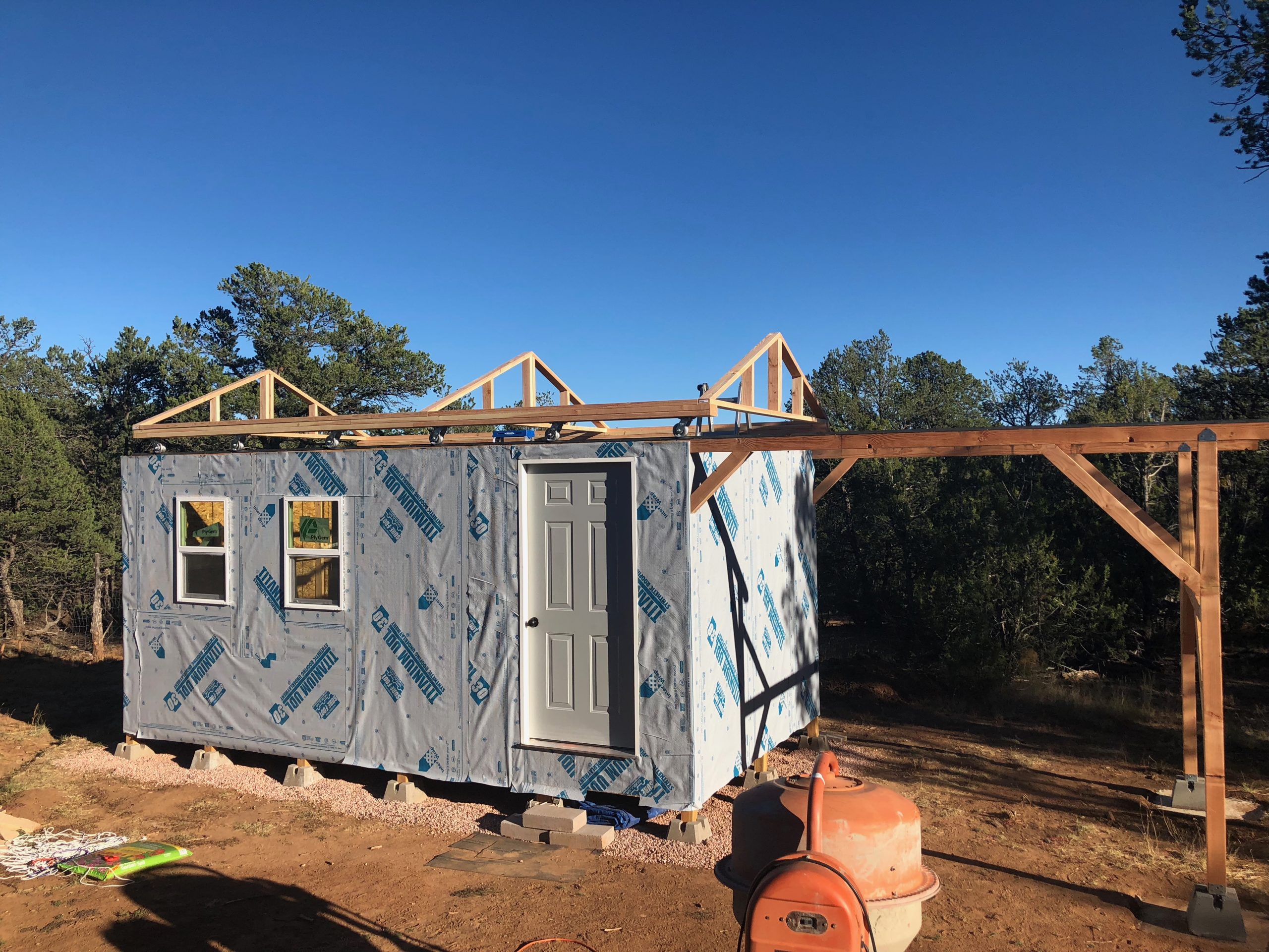
With the roof box tested and rolling smoothly, three custom-built trusses are installed to support the metal roofing. The two end trusses define the roof’s profile, while the third, offset from center, ensures the telescope can remain upright inside without being obstructed when the roof is closed—ideal for maintenance or alignment. Each truss is securely fastened to the roof box frame, keeping the structure both lightweight and strong for easy rolling.
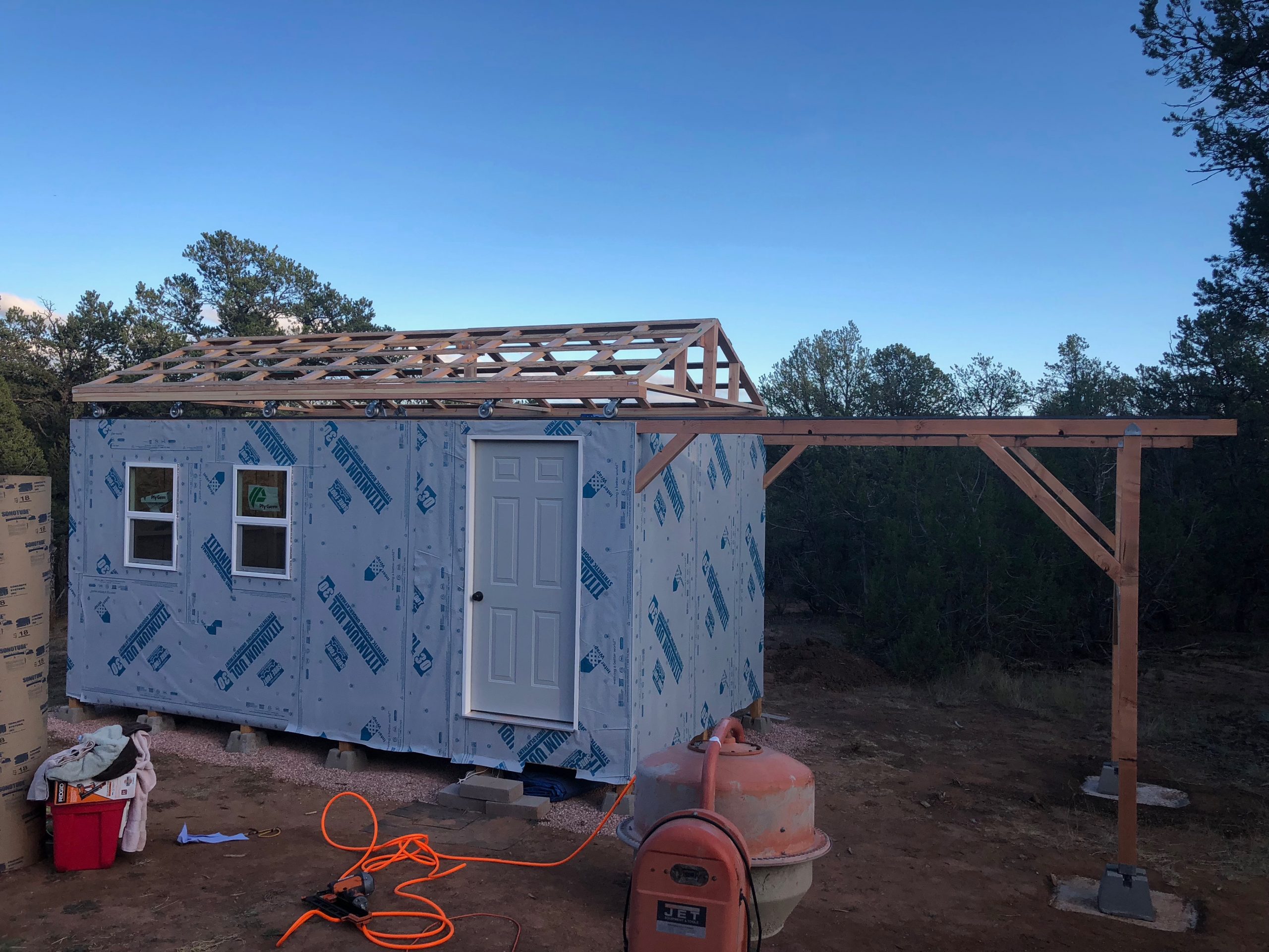
Horizontal support braces have been added across the roof trusses, locking them into alignment and providing the rigidity needed to mount the metal roofing panels. These cross ties strengthen the overall frame and also serve as convenient anchor points for securing the roofing material. The roll-off mechanism remains fully functional beneath the roof structure, which now has the stability and strength required for final panel installation.
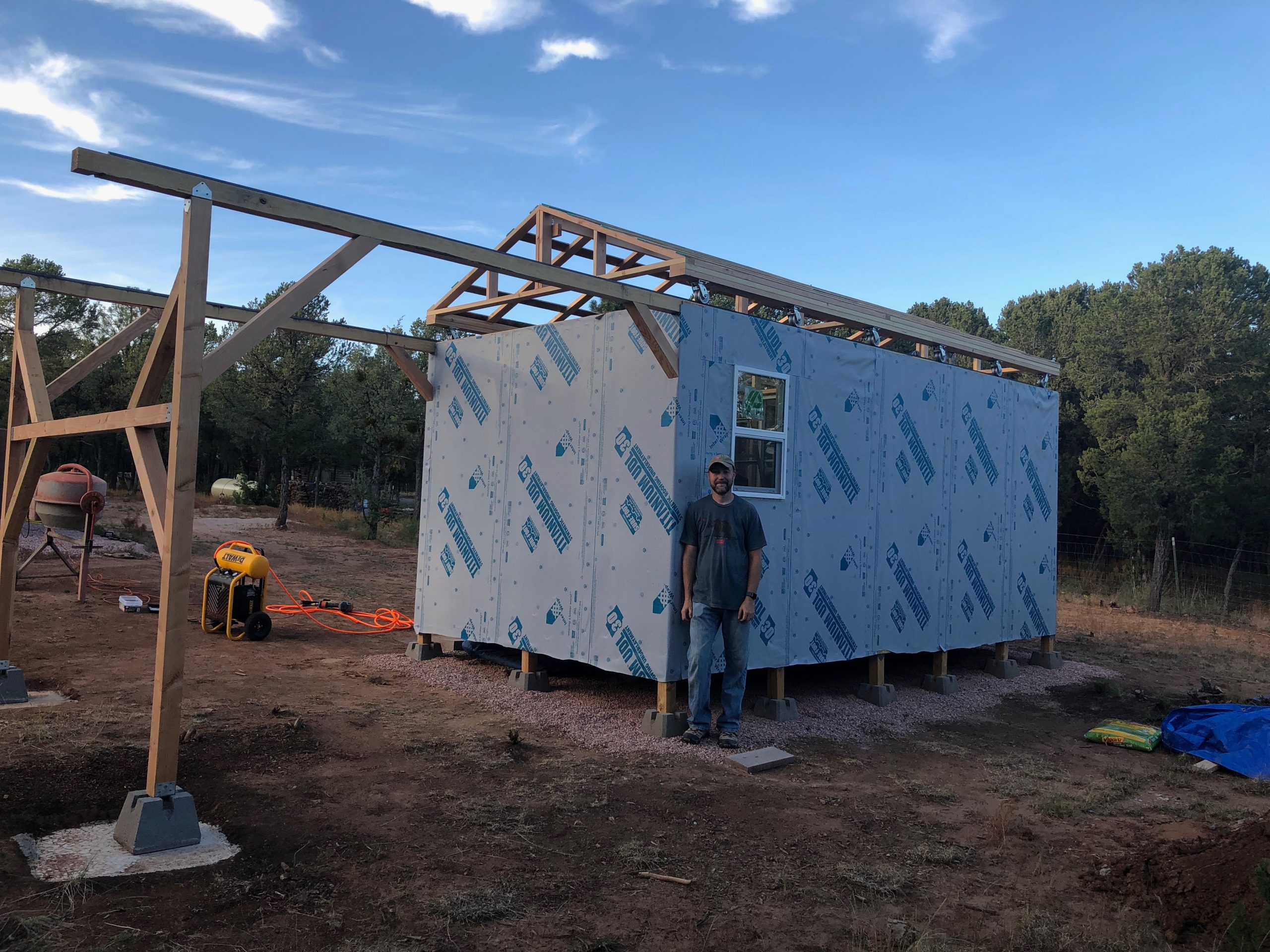
A rear view of the observatory shows the roof trusses fully braced and ready for metal paneling. The roll-off structure is now complete, with grooved rails and casters clearly visible along the wall top. This angle also highlights the gap between the roof and walls—later enclosed with vertical boards for weather protection. Standing in front is the builder himself (Brian), taking a well-earned moment beside the nearly finished roof frame.
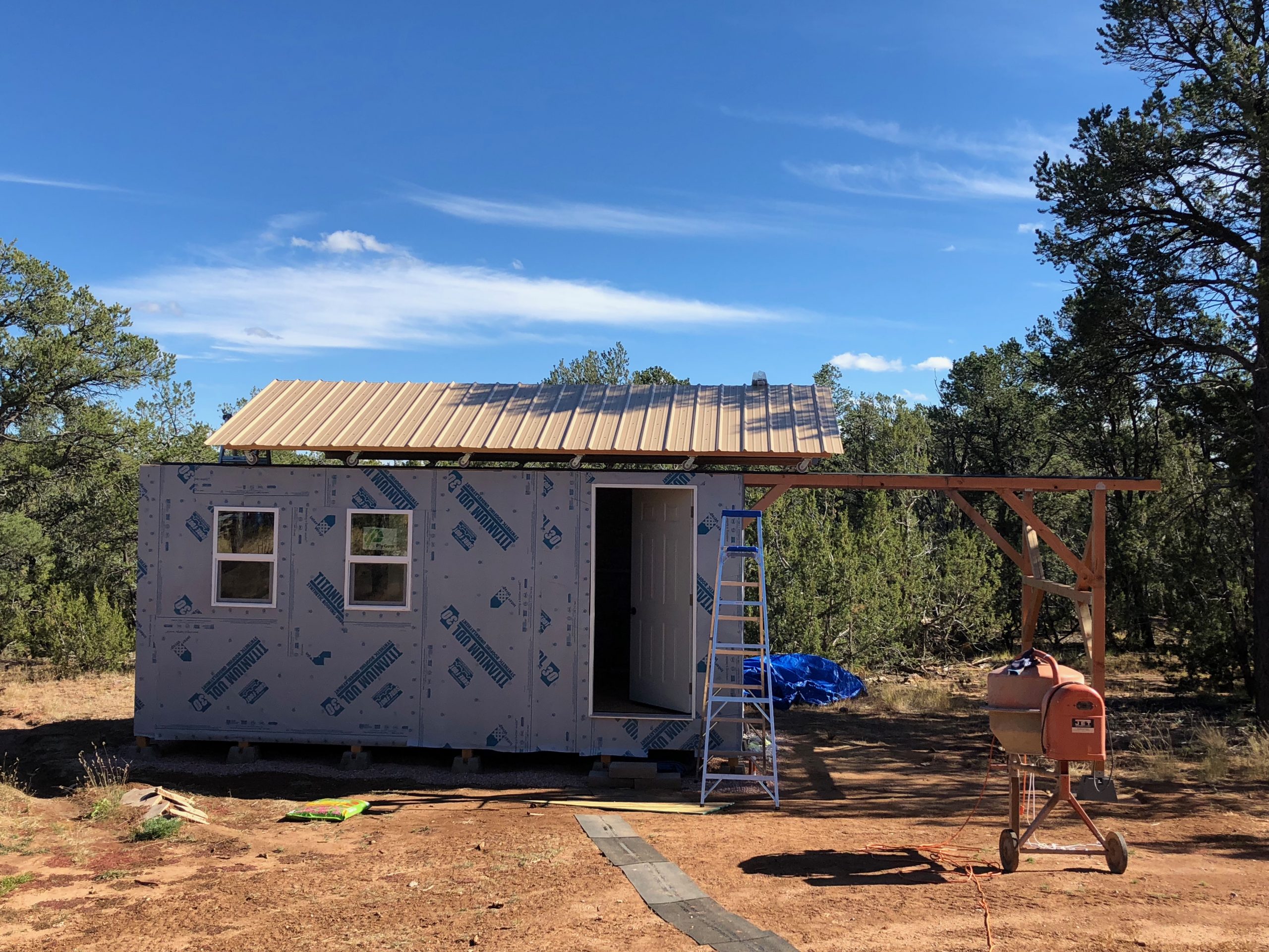
The metal roof panels are now fully installed on the truss structure, completing the upper shell of the observatory. The panels were laid out to minimize cuts, but several custom trims were still needed—cut cleanly with an air-powered sheet metal shear. A light-colored finish was chosen to reduce solar heating during the day, an important consideration for thermal stability inside the observatory. With the roof secured and balanced, the entire structure rolls cleanly on and off the support rails.
The roof is now fully open, with the completed structure—including ridge cap—gliding smoothly along the roll-off rails. In this position, the entire telescope room is uncovered for unobstructed sky access, while the warm room remains sheltered beneath the roof. This offset design provides the best of both worlds: clear observing space when needed and year-round weather protection for the control area. The installed roof cap completes the weatherproofing and gives the observatory a polished, professional finish.
The roof is shown in its fully closed position, completing the roll-off system’s operational cycle. When closed, the entire structure is protected from the elements, with all seams tightly aligned and the ridge cap securely covering the peak. The roof box glides into place with minimal effort, thanks to the well-aligned casters and angle iron tracks. With this phase finished, the observatory now has a robust, weatherproof, and fully mobile roof—ready for night skies above Mesa Vista.
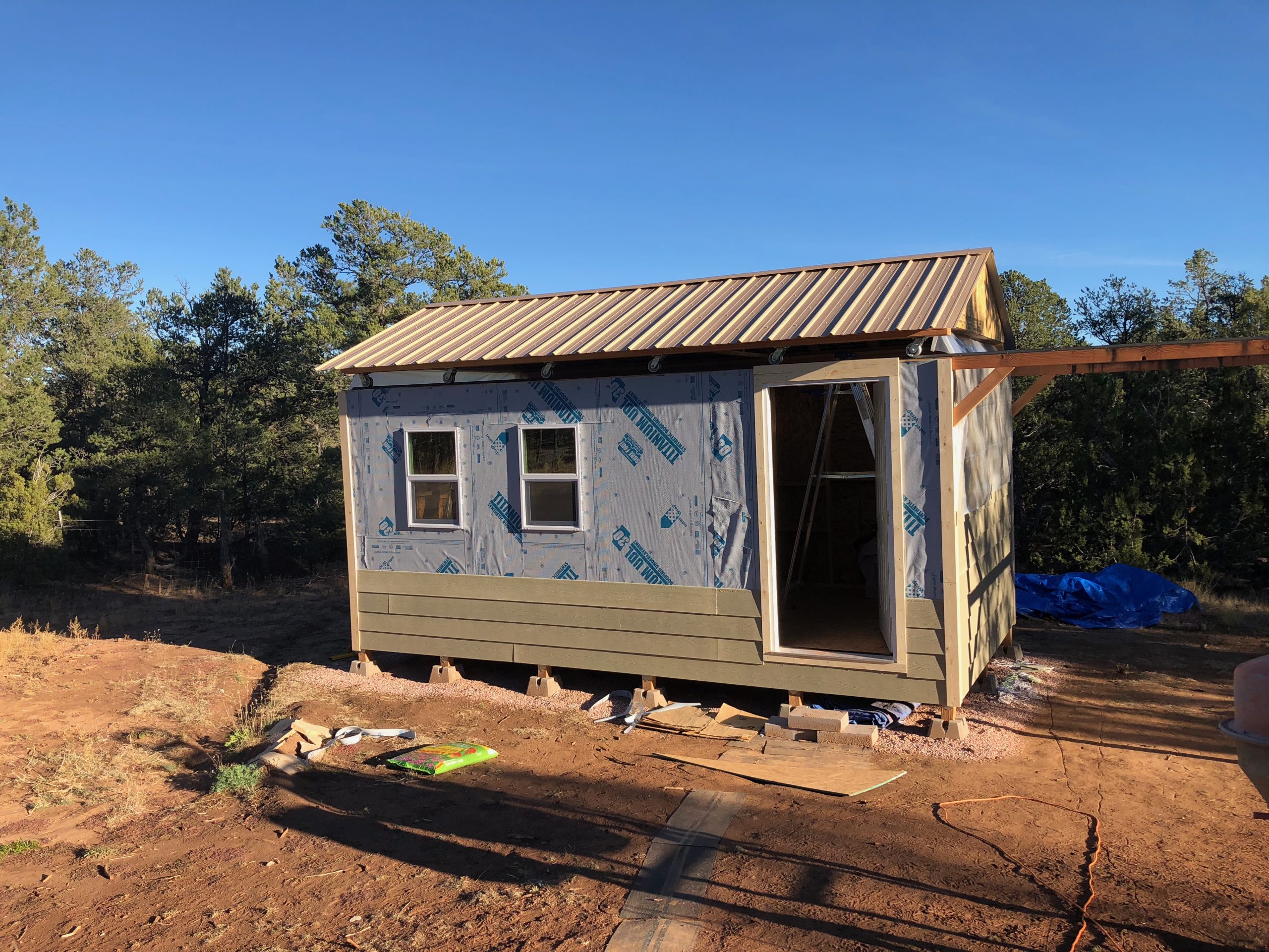
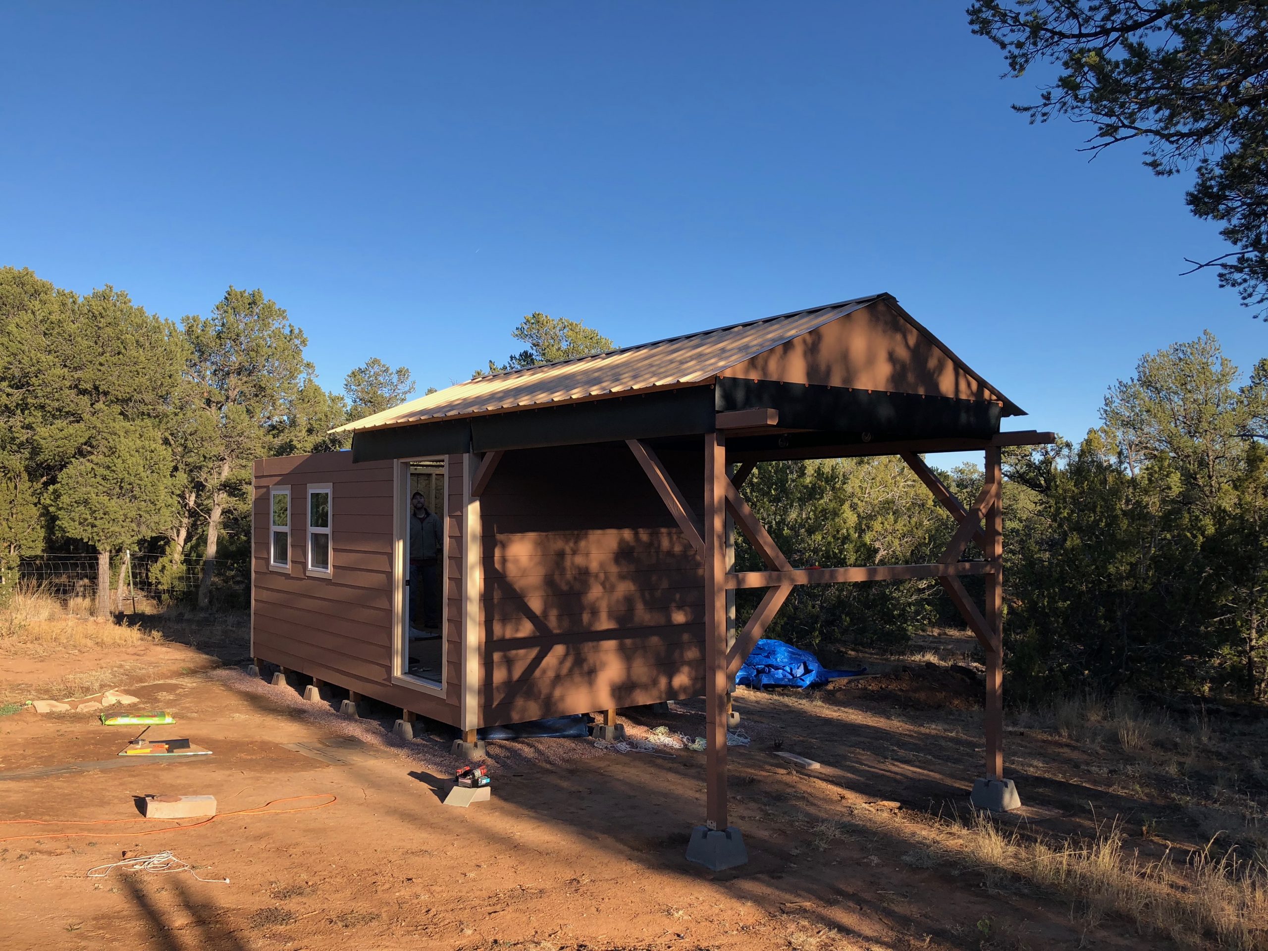
For the exterior cladding, I chose Hardie Plank siding for its durability, weather resistance, and low-maintenance performance—ideal for the high-desert climate of Pecos. The finishing process began with trimming out all corners and windows using clean 1×2 boards, establishing a defined edge for the siding. I started installation on the rear and side walls to minimize cutting, saving the more complex front wall—with its two windows and main entry door—for last. After siding was installed, I applied caulk around all trim and joints to ensure a tight weather seal, then painted the exterior in a color closely matched to my home’s stucco. For contrast, I painted the trim and door in a soft off-white shade similar to the metal roof. The roll-off beams and exterior braces were also painted for added protection. To temporarily seal the roof-to-wall gap, I tacked up rubber sheeting until permanent 1×12 boards could be installed, completing the enclosure.
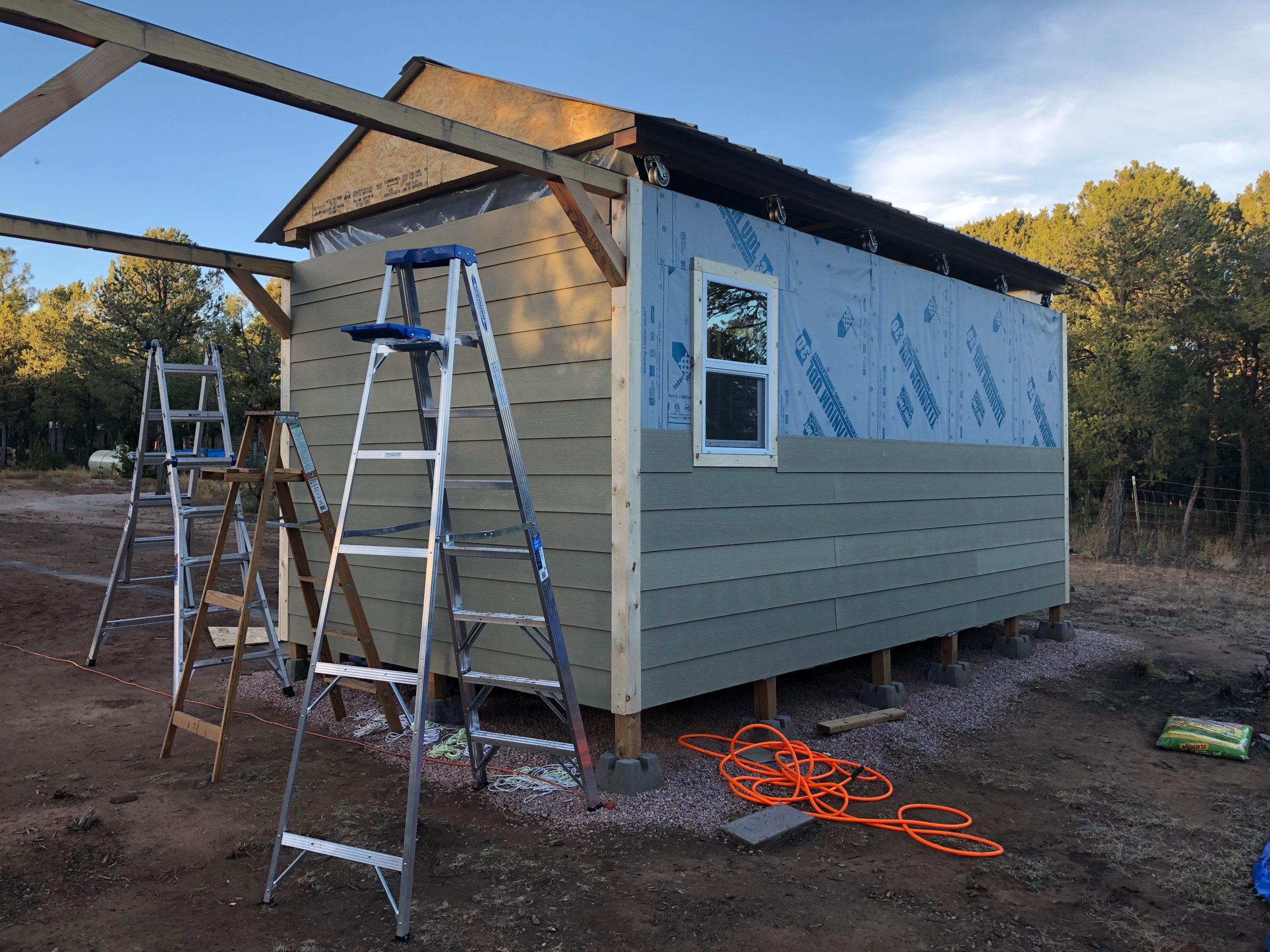
Installation of the Hardie Plank siding begins on the back and roll-off side of the observatory. The 1×2 trim boards have already been installed at the corners and around the window to create clean edges and a visual frame for the siding. Starting with the simpler rear and side walls helped streamline the process and minimize cuts. The stacked ladders are a familiar reminder of how much up-and-down work goes into a clean exterior finish!
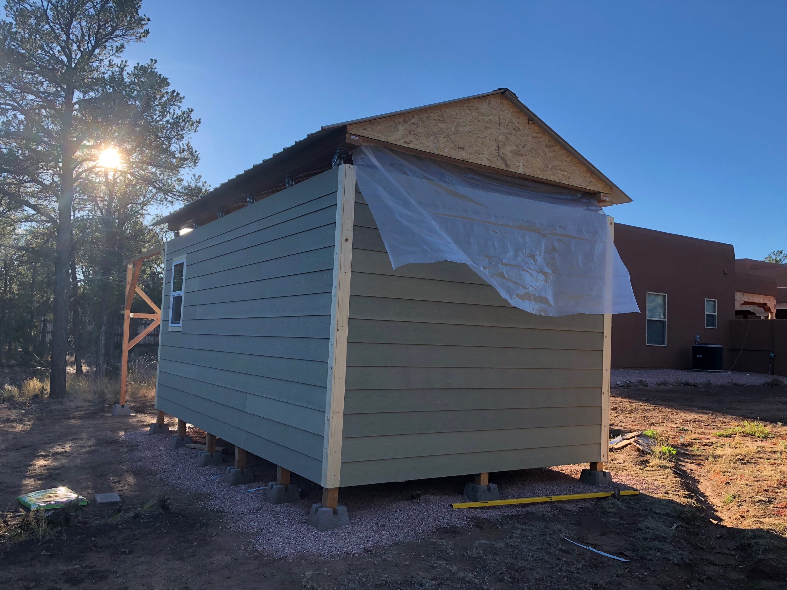
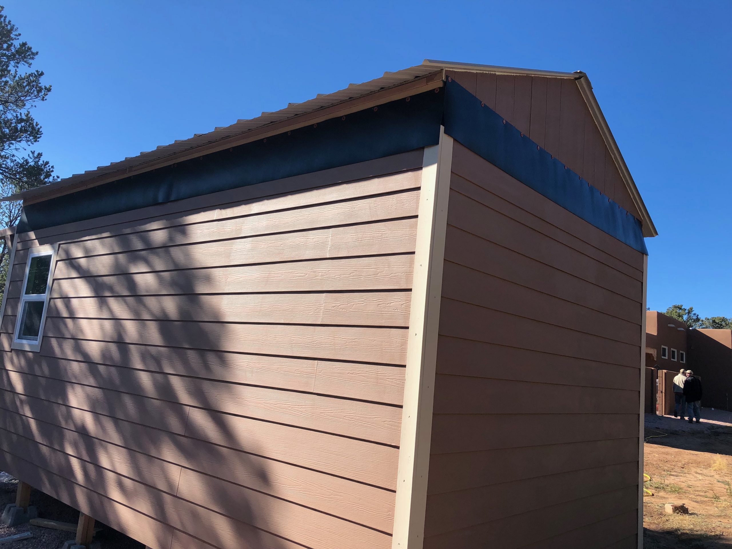
This view from the opposite side shows the completed Hardie Plank siding on both the rear and south walls, with all corner trim installed and aligned. The temporary plastic sheeting was tacked up for quick weather protection during New Mexico’s monsoon season—an essential precaution when you’re racing the forecast mid-build. The siding’s clean lines and fiber cement texture are already giving the observatory a polished, finished appearance.
Work progresses on the front wall, with Hardie Plank siding partially installed around the entryway and dual windows. This section required more precision due to the multiple cutouts, but the clean trim lines help maintain a balanced, finished look. With the roof fully complete and the siding wrapping around all sides, the observatory is starting to visually tie into its surroundings—and match the aesthetic of the main house just beyond view.
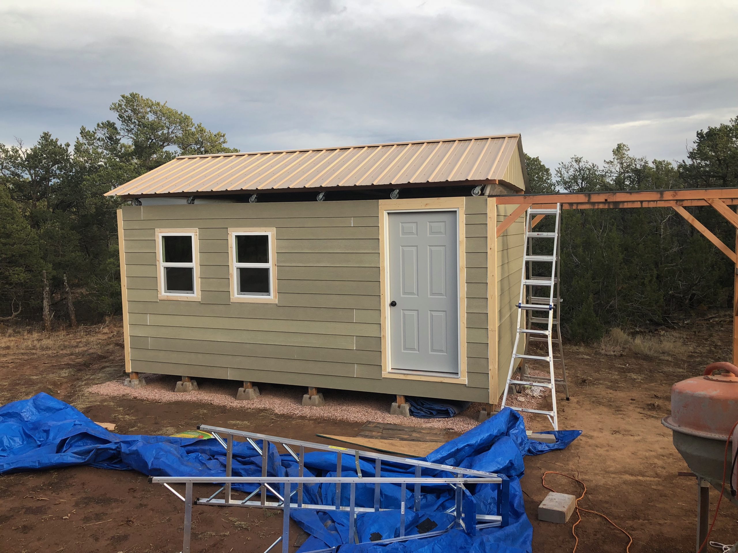
With all Hardie Plank siding now installed, the structure is fully enclosed and weather-ready. The 1×2 trim boards have been cut and mounted around the windows, door, and corners, but are still unpainted at this stage. The contrast between the trim and siding will become more pronounced once painted, but even in its current state, the observatory is starting to take on its final, cohesive form.
The siding and trim are now fully painted, giving the observatory a finished look that matches the surrounding home while blending into the New Mexico landscape. The earthy tone of the Hardie Plank complements the off-white trim, and the structure finally takes on its permanent exterior character. Temporary rubber sheeting has been installed in the gap between the moving roof and fixed walls to provide weather protection until the final 1×12 enclosure boards are added.
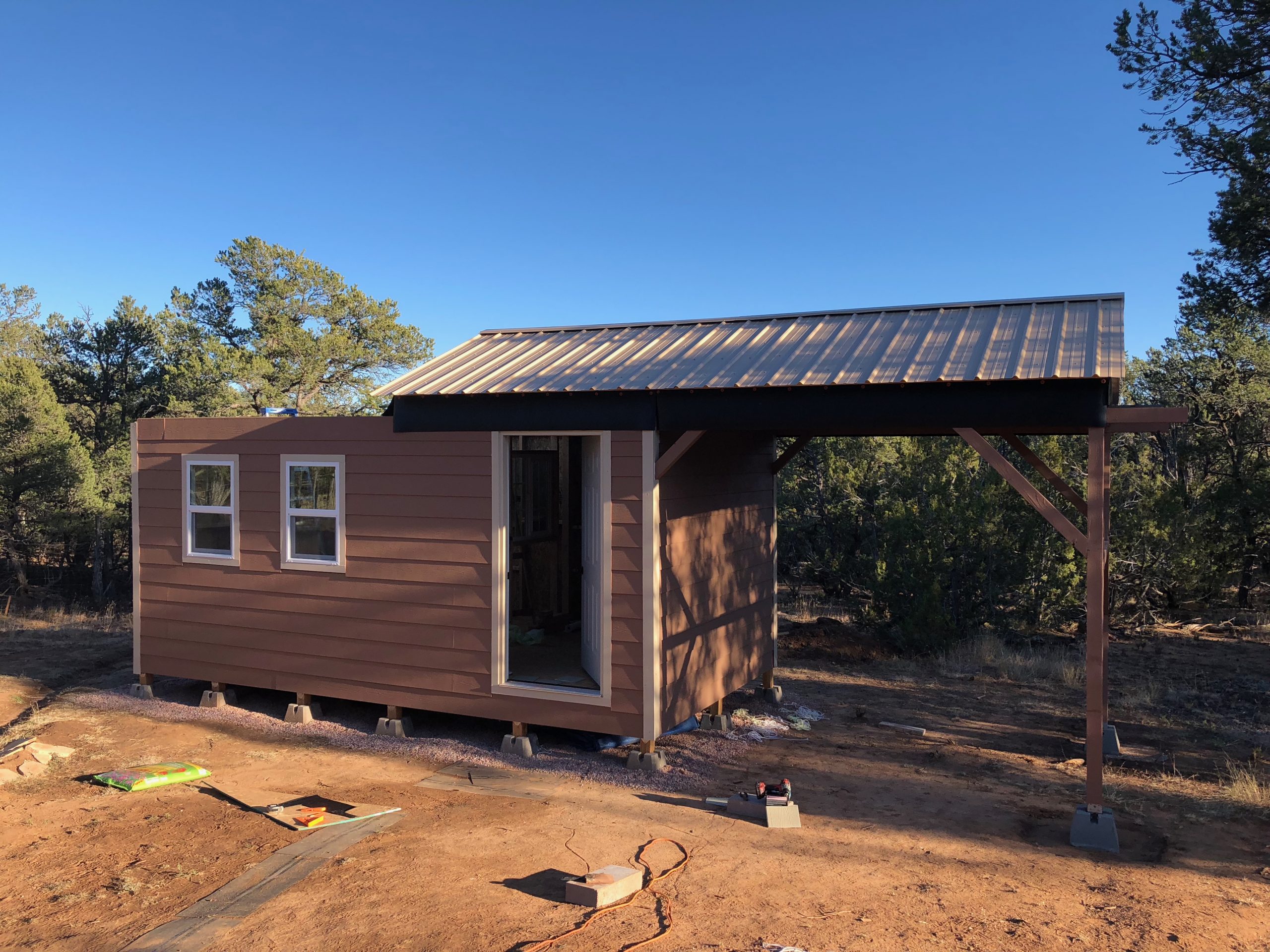
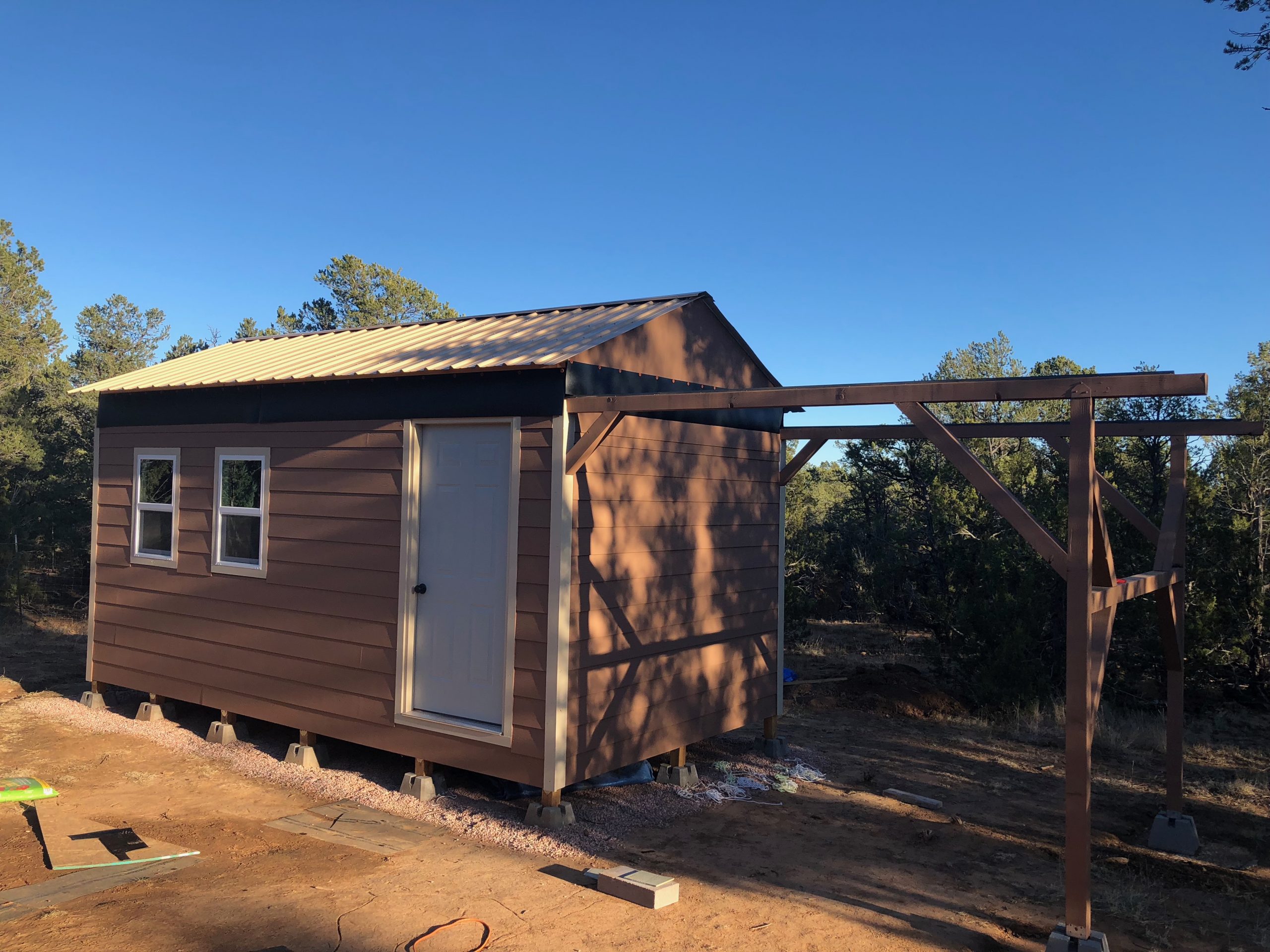
A front view of the completed exterior shows the fully painted siding, trim, and roll-off support structure. The warm-toned Hardie Plank and off-white trim echo the colors of the surrounding home, while the painted roll-off beams and braces blend seamlessly with the roofline. The observatory now feels like a permanent, integrated part of the property—both functional and visually cohesive with its high desert surroundings.
With the roof rolled fully open, the observatory reveals its dual-purpose design—leaving the telescope room completely exposed to the sky while the warm room remains enclosed. The painted roll-off structure and enclosure boards now blend seamlessly with the building’s color scheme. This view captures the observatory in its operational state, almost ready for a clear night’s imaging session under the Pecos sky.
With the roof closed and exterior work complete, the Mesa Vista Observatory stands fully weather-sealed and operational. The siding, trim, roof, and roll-off structure have all been finished and painted, leaving only minor cleanup and some additional gravel to be spread around the base and roll-off track area. With the exterior phase complete, the focus now shifts to the interior—where power, lighting, and functionality will bring the observatory fully to life.
With the exterior of the observatory complete, I shifted my focus to the interior. The first task was pre-wiring the electrical. When my house was built, I had a junction box installed on the exterior specifically so I could later run a trench and power cable to the observatory for permanent power.
Inside the observatory, I installed electrical boxes and switch boxes in logical locations, then ran Romex cable to each one. After trenching the power line from the house, I installed a junction box where the main feed enters the observatory.
The telescope room includes a weather-tight light fixture centered on each wall and a power outlet on each wall as well. The warm room has an overhead LED light, plus a smart “red light” that can be switched on for night use. I also installed enough outlets to power my computer gear, accessories, and optionally, a space heater or window A/C unit.
There’s also a single exterior light mounted near the roll-off roof rails to provide visibility when opening or closing the roof after dark.
Once power and lighting were installed, I turned my attention to finishing the interior. I may have gone a bit overboard here: I installed laminate wood flooring in both the telescope room and the warm room, which adds a more finished look and practical durability.
For the walls, I did something a little unconventional. While most people leave their telescope rooms uninsulated and unfinished to maintain better thermal equilibrium with the outside air, I chose to install wall coverings using a different style of laminate wood flooring. I attached the panels to the studs with a brad nailer, just like I did for the floors. The telescope room remains uninsulated, but the warm room is fully insulated for year-round comfort.
I finished out the space by trimming the windows, doors, and walls with simple 1×1 pine trim. With those final touches, the observatory itself was mostly complete. I installed the pier and telescope, and furnished the warm room with a small desk, shelving system, and all my computer gear. For networking, I extended the house’s Wi-Fi signal with a range extender, providing fast and reliable connectivity out in the observatory. I also installed shelves in the telescope room and latches to secure the roof when both open and closed.
Early stages of interior wiring in the warm room. I installed receptacle and switch boxes in carefully planned locations, making sure everything would be within easy reach once the room was furnished. This photo shows the framed partition separating the warm room from the telescope room, with a dedicated window that lets me monitor the scope from indoors. Most of the boxes you see here will later serve power outlets, lighting controls, and the smart red light. Planning the electrical layout at this stage helped ensure the space would be both comfortable and efficient once in operation.
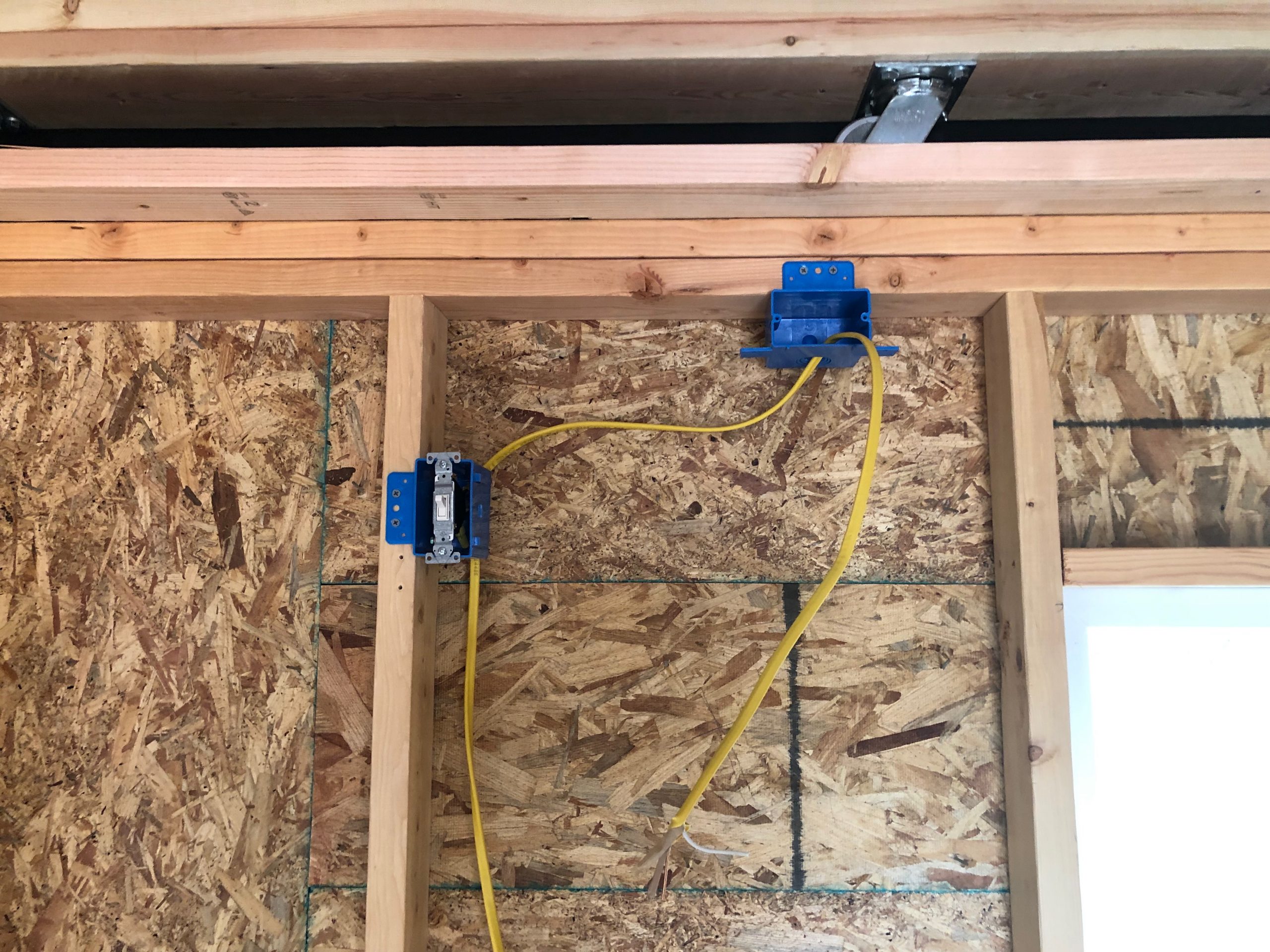
This switch and electrical box control the red light in the warm room — a smart light specifically chosen to preserve night vision while the observatory is in use. I wanted this space to be as functional as possible during imaging sessions, so thoughtful lighting was key. The wiring runs neatly up to the weather-sealed overhead light housing, visible at the top, and continues down to the outlet box below, which powers other warm room equipment. Every component here was placed deliberately to support both comfort and dark-sky discipline.
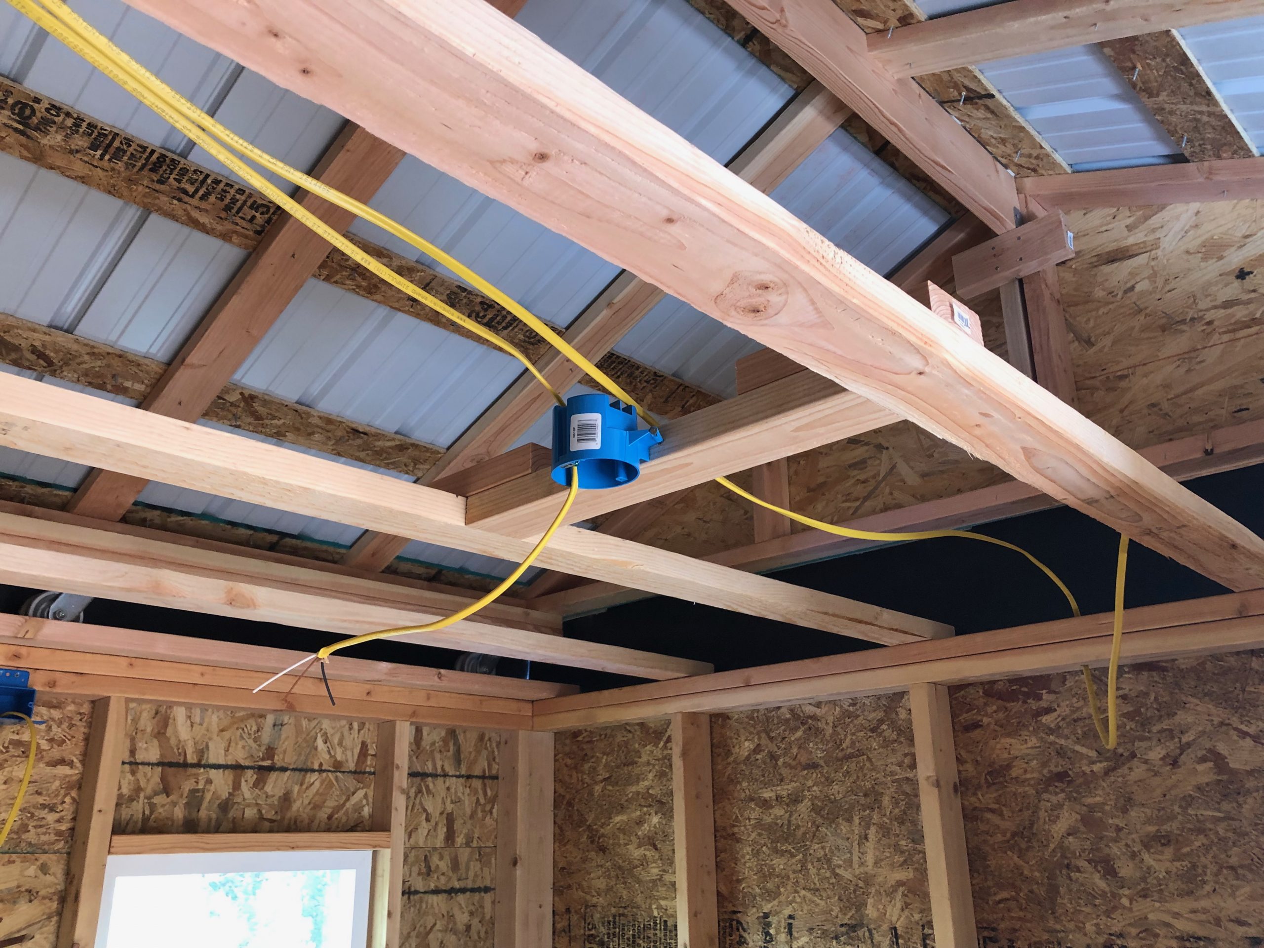
Running cable for two important fixtures here: the ceiling-mounted LED light in the warm room and the outdoor light by the roll-off rails. The indoor fixture provides general lighting, while the exterior one ensures safe operation of the roof at night—especially helpful when observing sessions end in total darkness. Routing the wiring through the warm room ceiling joists took some planning but allowed for a clean, tucked-away look once everything was enclosed.
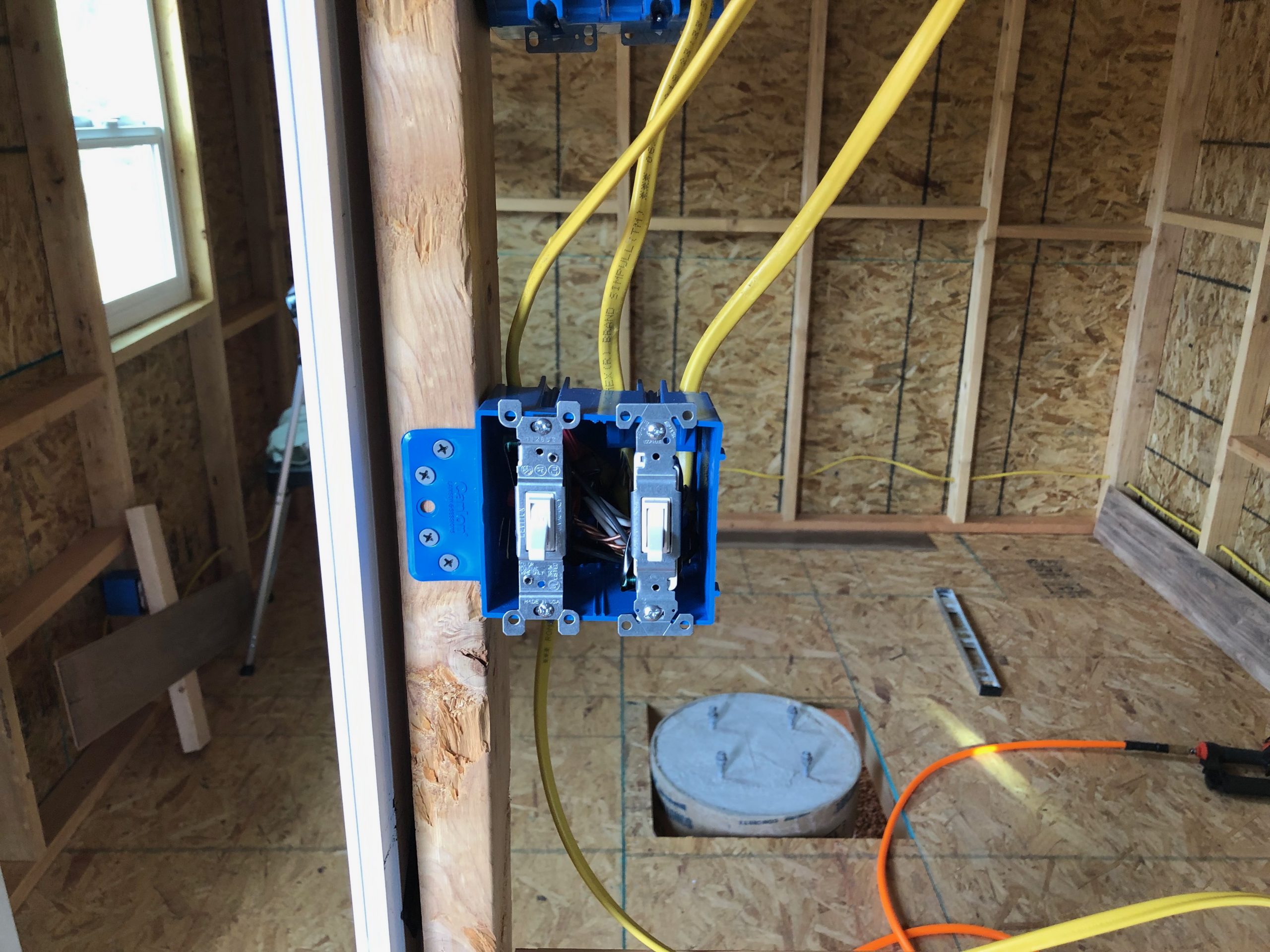
This double-gang switch box handles lighting for both the warm room and the exterior rail-side light. The left switch controls the overhead LED inside, while the right one operates the outdoor fixture—handy when rolling the roof off in low light. At this stage, everything’s wired up but still open for inspection and testing before covering it all up with wall paneling. You can also see the telescope pier foundation in the background, waiting for its moment.
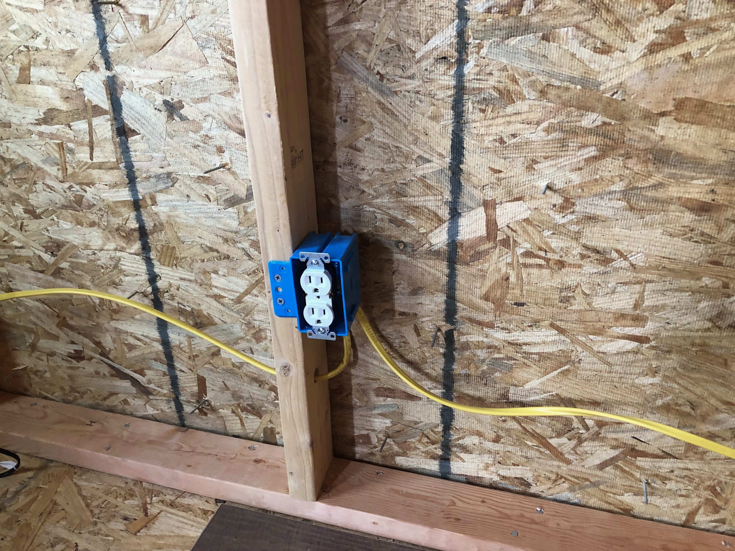
One of the dedicated electrical outlets in the telescope room, strategically placed to handle power needs for mounts, dew heaters, cameras, and other gear. Each wall in the scope room gets its own outlet to avoid cord chaos later. The wiring is still in rough-in stage here—clean, organized, and ready for testing before wall finishes go up.
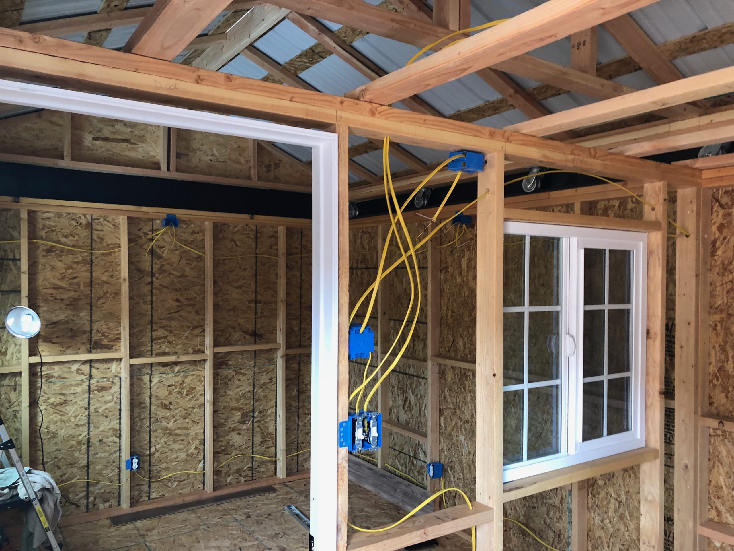
Most of the electrical rough-in is complete at this stage. You can see receptacle boxes spaced around the telescope room to ensure convenient access to power from any side. Each wall also has its own lighting box, perfectly centered, ready for weather-tight LED fixtures. Toward the middle, the bundle of Romex includes wiring for the main scope room light and the red light—ideal for preserving night vision during observing sessions.
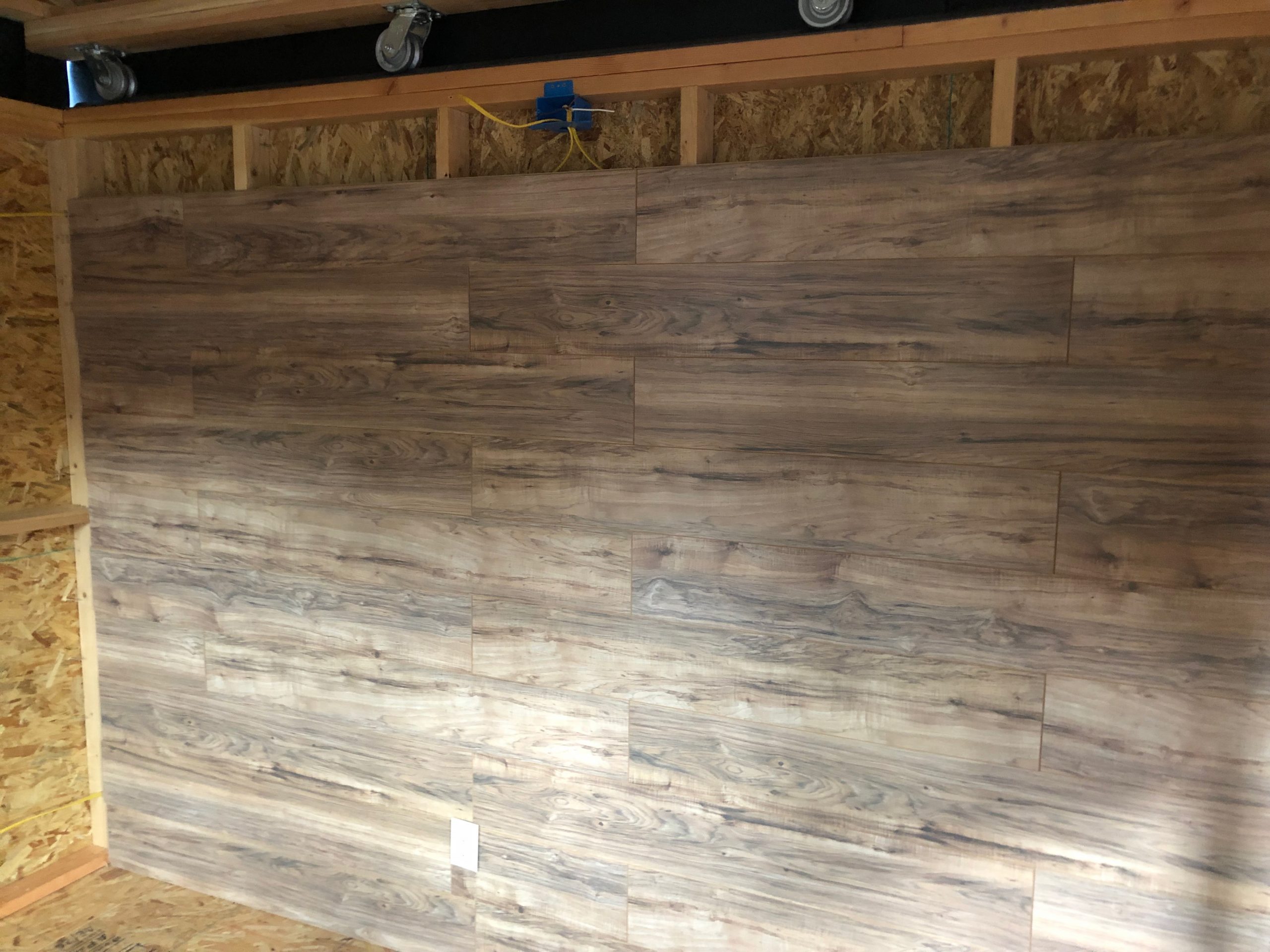
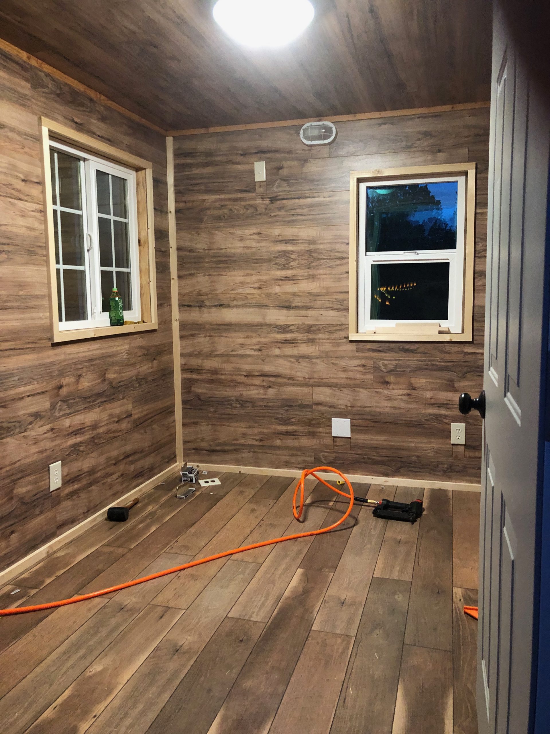
With the electrical rough-in done, wall covering begins in the telescope room—starting with this laminate plank paneling. While most folks leave the walls bare for better thermal equilibrium, I opted for a more finished look. These panels add warmth (visually, not thermally!) and give the room a polished feel. You can spot one of the electrical outlets already trimmed out and ready for final installation.
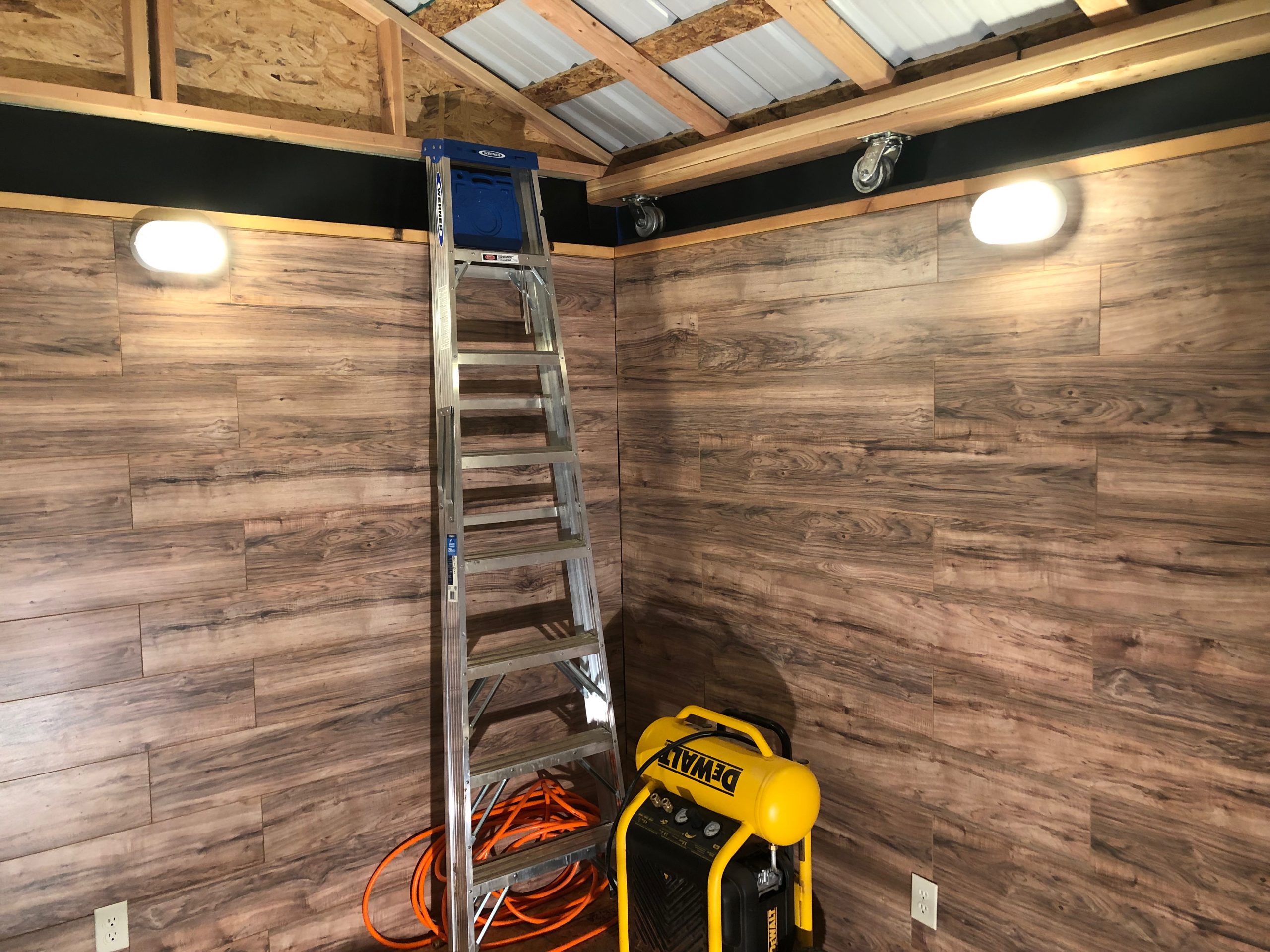
The telescope room is really coming together—laminate wall paneling is fully installed, wall outlets are trimmed out, and the weatherproof light fixtures are up and powered on. This shot gives a great sense of how finished the space feels now. Even though the ladder and tools are still out, we’re solidly into the “it’s becoming real” phase of the build.
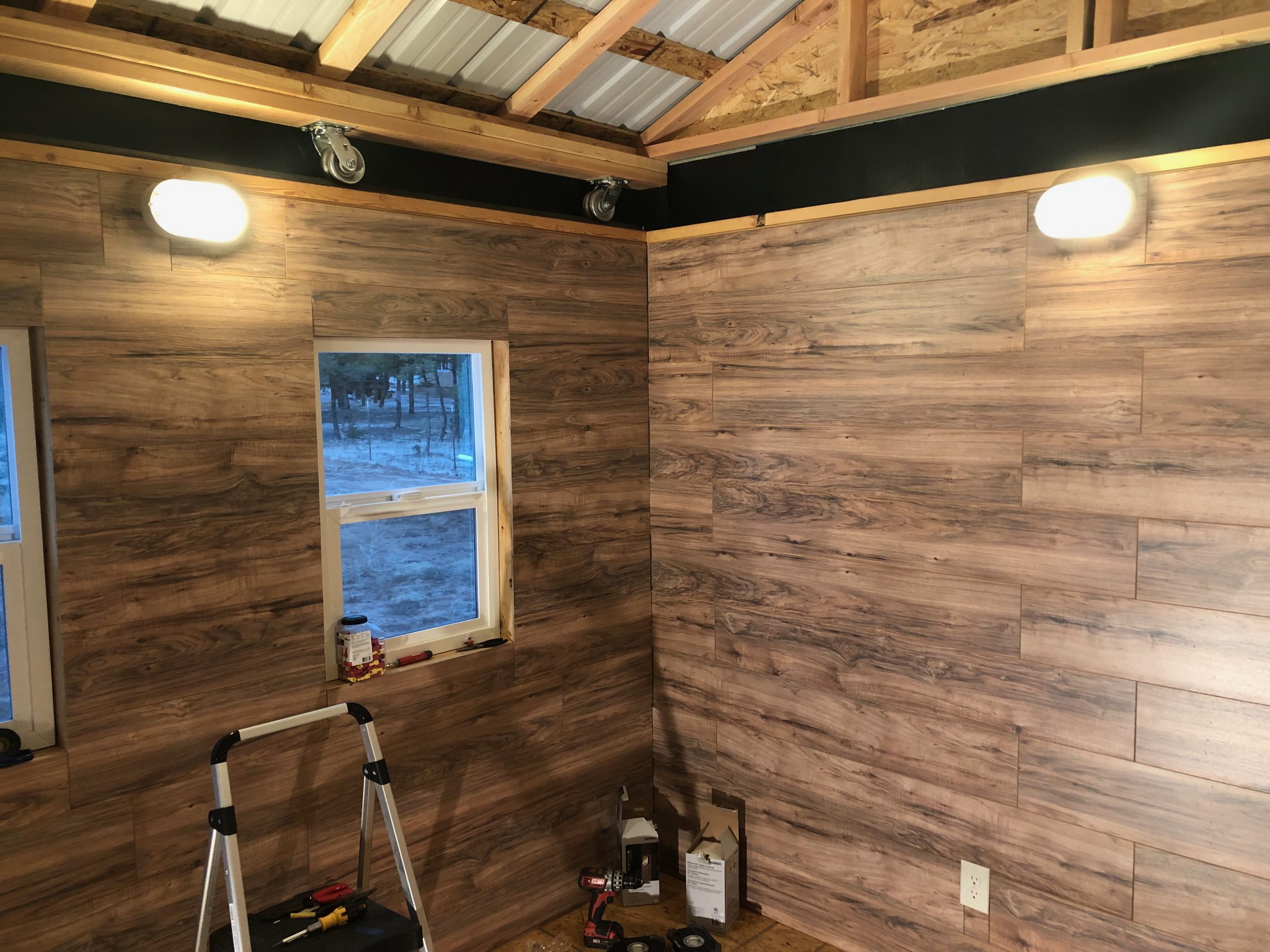
Another view from inside the telescope room—this time looking toward the front wall. The paneling is done, the lights are glowing, and the outlets are live. The windows haven’t been trimmed yet, but you can already see how much natural light they’ll bring in during the day. It’s starting to feel more like a finished space and less like a construction project.
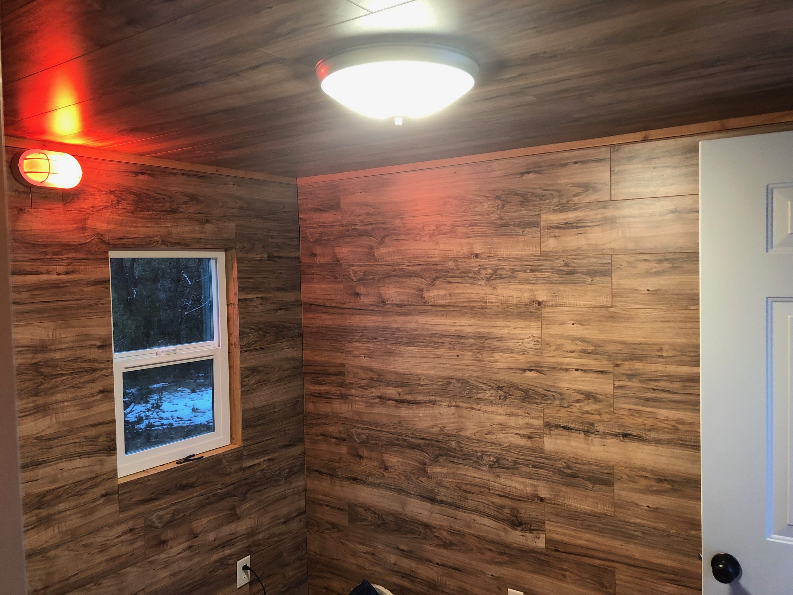
Inside the warm room, looking toward the back window. The red astronomy light is now installed and fully operational—it’s dimmable and the color temperature is adjustable, all controllable from my computer or phone. The overhead light adds general illumination when night vision isn’t a concern. The laminate paneling carries through here as well, and the door on the right is the main entry into the observatory.
A view into the warm room from the entry door. The 1×1 pine trim is being installed around the doors, windows, and corners, giving the space a clean, finished look. The laminate flooring is also in place, adding warmth and durability. A few tools and trim pieces are still scattered about as the finishing touches come together.
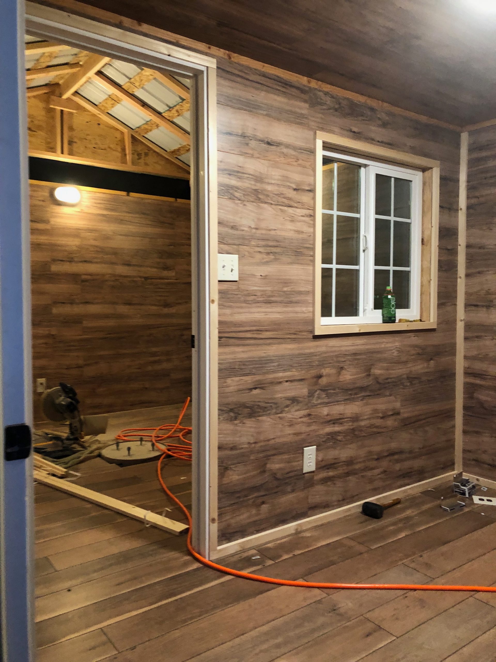
A view from the now-complete warm room, looking through the doorway into the telescope room. You can see the 1×1 pine trim starting to go up in the observatory space as well. The wall paneling and flooring are fully installed in both rooms, and tools are still out as the trim work nears the finish line.
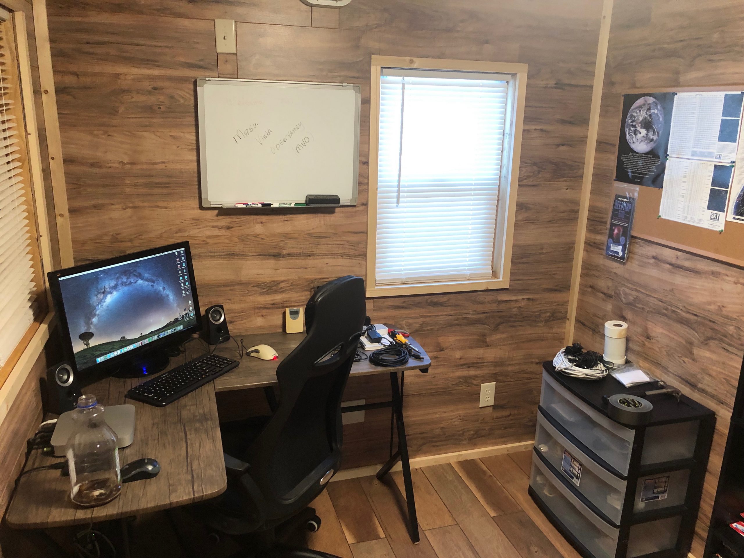
The warm room fully outfitted and operational, featuring a computer desk setup for telescope control and image processing. With blinds on the windows, trim completed, and organization underway, the space is both functional and comfortable—ready to support long observing sessions and data analysis deep into the night.
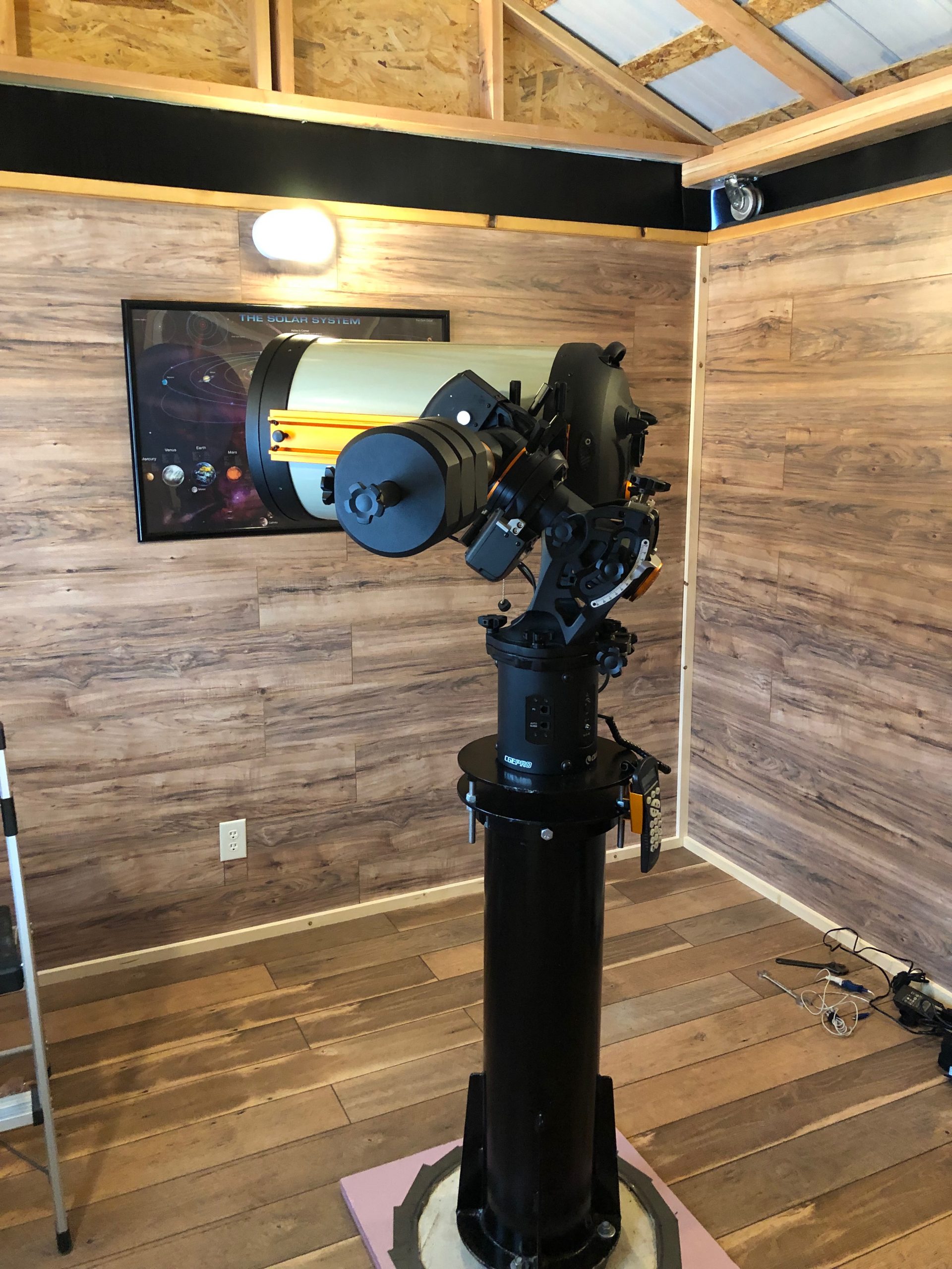
With the telescope now mounted on the permanent pier, the observatory enters its final stage of readiness. The Celestron EdgeHD 14 and CGE Pro mount are fully installed, aligned, and ready for first light under the dark skies of Pecos. The warm wood walls, finished flooring, and framed solar system poster round out the space, blending science and comfort in this fully operational Mesa Vista Observatory.
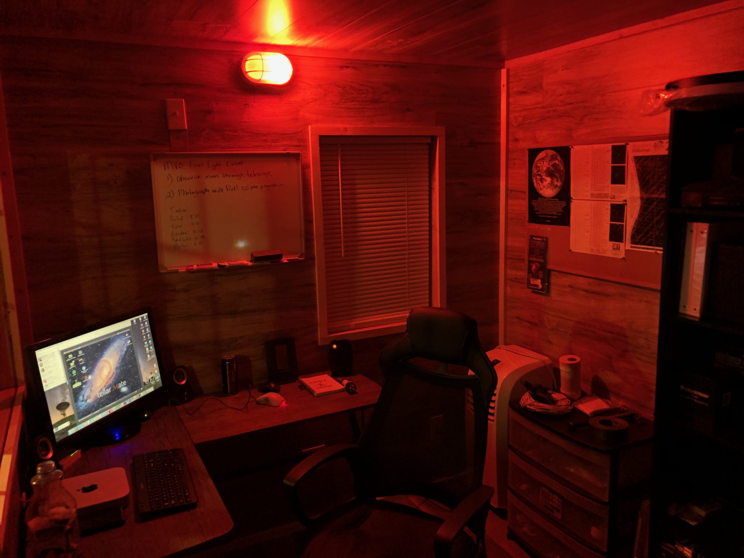
The warm room at night, illuminated by soft red lighting to preserve night vision. The glow is fully dimmable and the color temperature can be adjusted directly from a phone or computer—perfect for imaging sessions that go late into the night. Everything needed for control and comfort is right at hand.
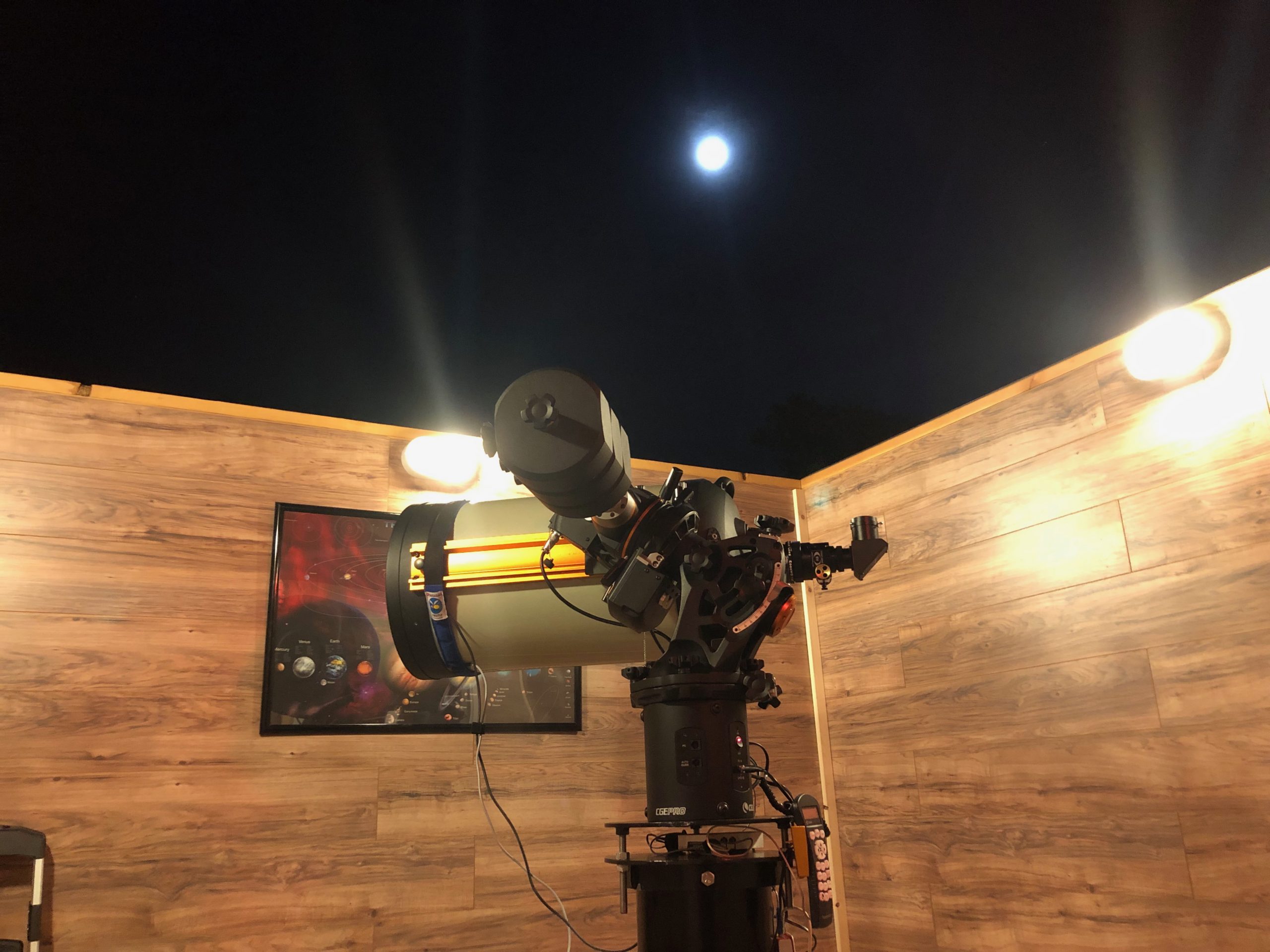
The telescope room at night with the roof rolled off, revealing a bright full moon overhead. The telescope is parked and ready for a night of observing. The white lights will soon be turned off, and the red light switched on—preserving night vision as the session begins under the stars.
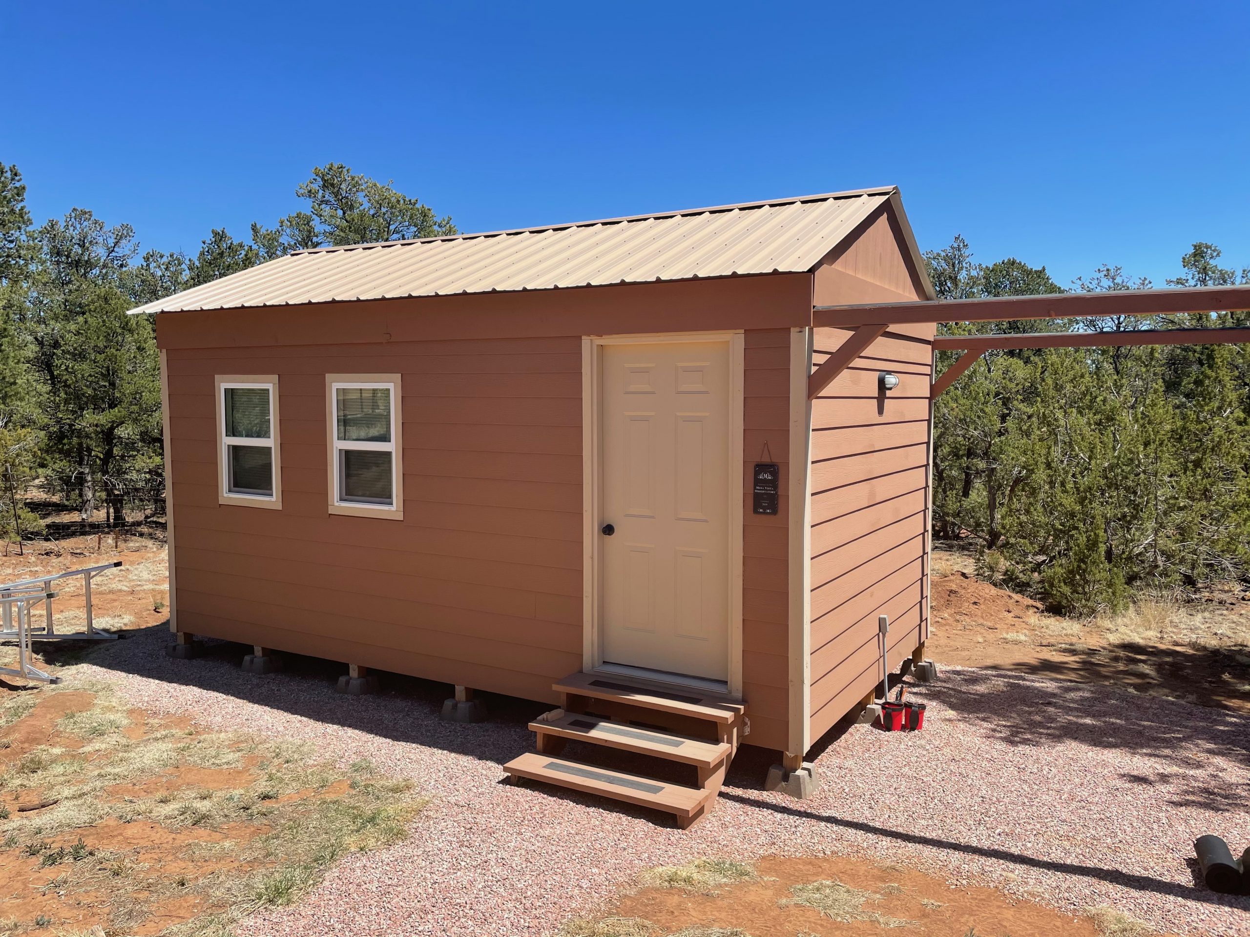
The finished Mesa Vista Observatory under a flawless New Mexico sky. With the roof closed and exterior complete, the old temporary rubber sheeting over the roof rails has been replaced by clean, fitted 1×12 boards—blending function and form into a crisp, final look. The observatory is ready.
© 2025 Enchanted Astronomy. All rights reserved.